3 Stage Conveyor.pdf - 第28页
TECH NICAL RE FERE NCE SEQUEN CES 1.22 High Throughput Conveyor Manual Chapter Issue 2 May 02 conveyor wher e it is hel d by the conveyor board stop. Three S tage Fast In thre e stage fast m ode, the operation is the sam…
TECHNICAL REFERENCE
SEQUENCES
Chapter Issue 2 May 02 High Throughput Conveyor Manual 1.21
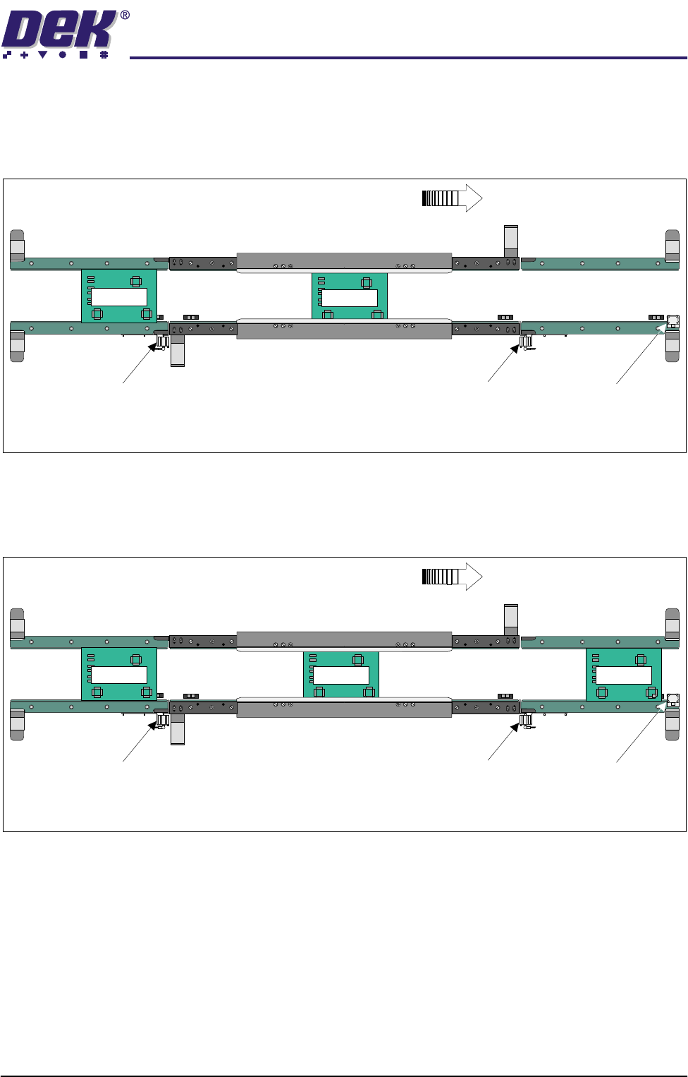
Three Stage Normal In three stage normal mode the upline auxiliary conveyor transports Board 1 to
the print station conveyor where the board is processed. With Board 1 in print
position, Board 2 is dispensed from the upline machine. When Board 2 arrives
at the sensor, at the end of the upline auxiliary conveyor, the transport belts stop.
After the print cycle, the Board 1 is then transported to the downline auxiliary
conveyor. When the leading edge of the board activates the sensor, at the end
of the downline auxiliary conveyor, a signal is sent allowing Board 2 to enter the
print station and Board 3 to enter on the upline auxiliary conveyor.
Providing the downline machine is ready, the first board can leave the downline
auxiliary conveyor and the cycle be repeated. If the downline machine is busy,
the second board is printed and transported to the end of the print station
K
E
Y
E
N
C
E
P
Z
-4
2
L
Board 1
K
E
Y
E
N
C
E
P
Z
-4
2
L
K
E
Y
E
N
C
E
P
Z
-
4
2
L
K
E
Y
E
N
C
E
P
Z
-
4
2
L
WARNING SHARP EDGE
PATENT No 5157438
WARNING SHARP EDGE
PATENT No 5157438
Print StationConveyor
Board Stop
Downline Conveyor
Board Stop
Upline Conveyor
Board Stop
Plan View of Board Positioning with Downline Machine Delay (Three Stage Mode)
Board Direction from Left to Right
K
E
Y
E
N
C
E
P
Z
-4
2
L
K
E
Y
E
N
C
E
P
Z
-
4
2
L
Board 2
K
E
Y
E
N
C
E
P
Z
-
4
2
L
Board 2
K
E
Y
E
N
C
E
P
Z
-4
2
L
K
E
Y
E
N
C
E
P
Z
-
4
2
L
K
E
Y
E
N
C
E
P
Z
-
4
2
L
WARNING SHARP EDGE
PATENT No 5157438
WARNING SHARP EDGE
PATENT No 5157438
Print StationConveyor
Board Stop
Downline Conveyor
Board Stop
Upline Conveyor
Board Stop
Plan View of Board Positioning with Downline Machine Delay (Three Stage Mode)
Board Direction from Left to Right
K
E
Y
E
N
C
E
P
Z
-
4
2
L
Board 1
K
E
Y
E
N
C
E
P
Z
-4
2
L
K
E
Y
E
N
C
E
P
Z
-
4
2
L
Board 3
TECHNICAL REFERENCE
SEQUENCES
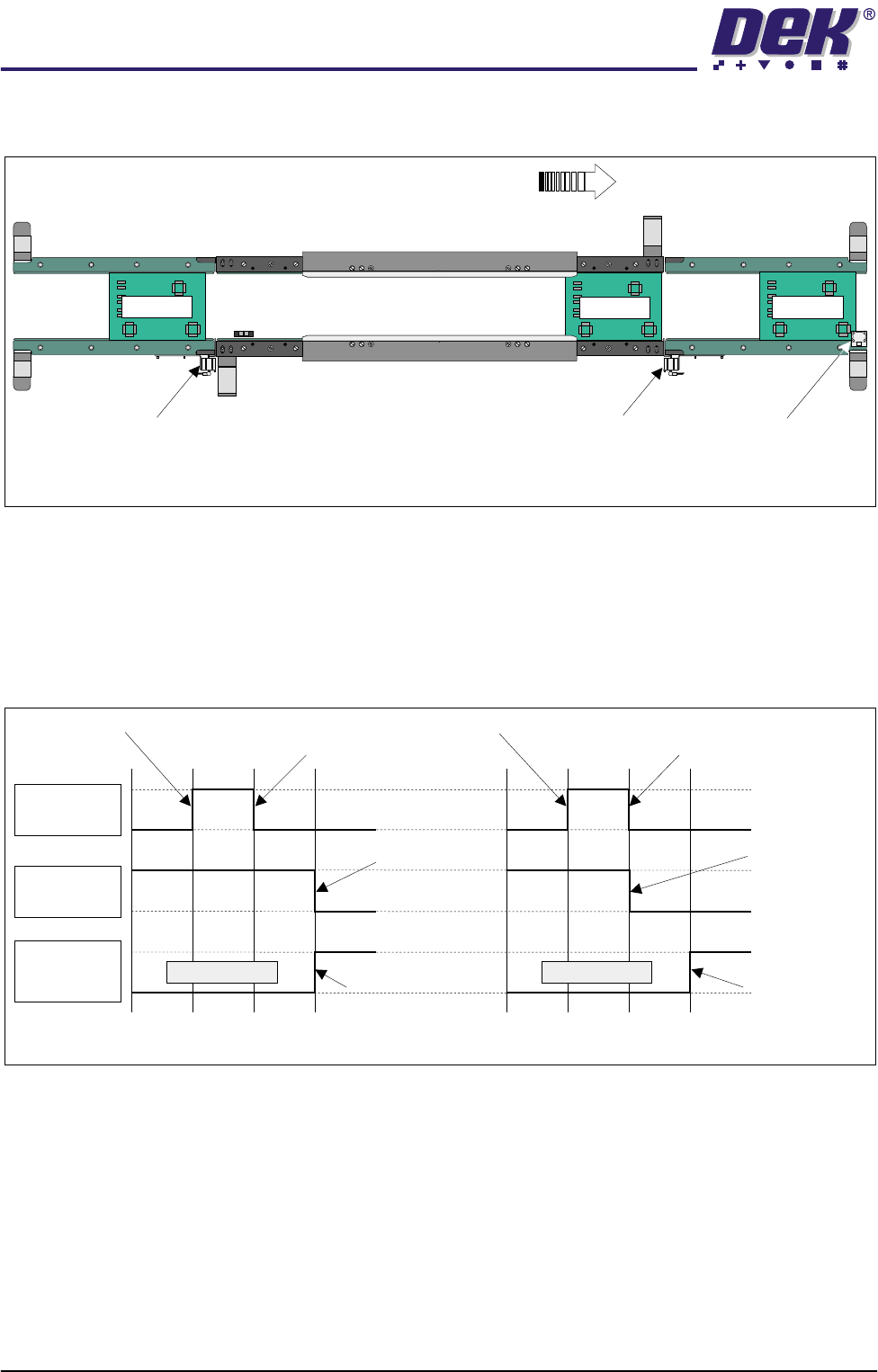
1.22 High Throughput Conveyor Manual Chapter Issue 2 May 02
conveyor where it is held by the conveyor board stop.
Three Stage Fast In three stage fast mode, the operation is the same as three stage normal mode
with one exception. The second board is transported on to the print station
when the trailing edge of the first board passes the board at right opto situated
at the end of the print station conveyor. This is achieved by the downline
conveyor returning a ‘Busy’ signal back to the centre as soon as it detects that
its ‘Board Available’ input has gone ‘low’, which completes a downline transfer
as far as the print station is concerned.
Figure 1-16 Normal/Fast Mode Timing Chart
K
E
Y
E
N
C
E
P
Z
-
4
2
L
K
E
Y
E
N
C
E
P
Z
-
4
2
L
K
E
Y
E
N
C
E
P
Z
-
4
2
L
K
E
Y
E
N
C
E
P
Z
-
4
2
L
WARNING SHARP EDGE
PATENT No 5157438
WARNING SHARP EDGE
PATENT No 5157438
Print Station Conveyor
Board Stop
Downline Conveyor
Board Stop
Upline Conveyor
Board Stop
Plan View of Board Positioning with Downline Machine Delay (Three Stage Mode)
Board Direction from Left to Right
Board 3
Board 2
Board 1
Board
Available I/P
Downline
Auxiliary
Sensor I/P
Downline
Available O/P
Belts Running
Normal Mode
Board Available Upline Board Leaves
Upline Machine
Belts Running
Fast Mode
Board Available Upline Board Leaves
Upline Machine
Negative Edge
Frees Upline
Machine
Negative Edge
Frees Upline
Machine
Board Activates
Downline Auxiliary
Sensor
Board Activates
Downline Auxiliary
Sensor

TECHNICAL REFERENCE
ADJUSTMENTS & SETTINGS
Chapter Issue 2 May 02 High Throughput Conveyor Manual 1.23
ADJUSTMENTS & SETTINGS
Rail Lifted Sensors 1. From the run menu, select Maint.
2. Select Diagnost.
3. Select Rising Table. Select Select Module.
4. Select Home Rising Table. Select Run Diagnost, ensure the table moves
to its home position.
5. Select Exit.
6. Select Rail System. Select Select Module.
7. Select Home Rail Width. Select Run Diagnost, ensure the rear rail moves
to its home position.
8. Place a 0.5mm feeler gauge between the shock absorber on the rear right
rail transport leg and the rail stop bar (clatter bar). Adjust the vane bracket
using a 2.5mm Allen key, so that the sensor LED is On with a 0.5mm feeler
gauge fitted and Off with a 0.7mm feeler gauge fitted. Lock adjusting
screws.
9. Repeat Step 8 for left hand end of rear rail.
10. Select Drive Rail To Board Width. Select Run Diagnost.
Right Rail
Transport Leg
Main Rear
Rail
Front View of Rail System
Left Rail
Transport Leg
Linear Bearing
Feeler Gauge
Rail Stop Bar
(Clatter Bar)
Opto Vane
Bracket
Opto Vane
Opto
Shock Absorber
Sensor LED
Enlarged View of Right Rail Opto