3 Stage Conveyor.pdf - 第36页
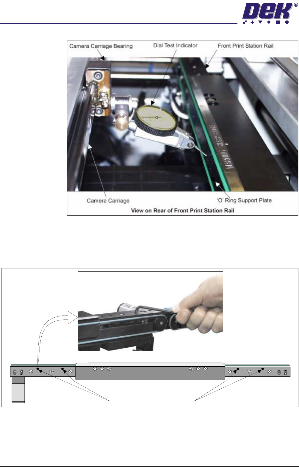
TECH NICAL RE FERE NCE ADJUS TMEN TS & SETTI NGS 1.30 High Throughput Conveyor Manual Chapter Issue 2 May 02 6. Using the D.T .I. check the front rail p arallelism to c amera carriage rail over the length of the &apo…
TECHNICAL REFERENCE
ADJUSTMENTS & SETTINGS
Chapter Issue 2 May 02 High Throughput Conveyor Manual 1.29
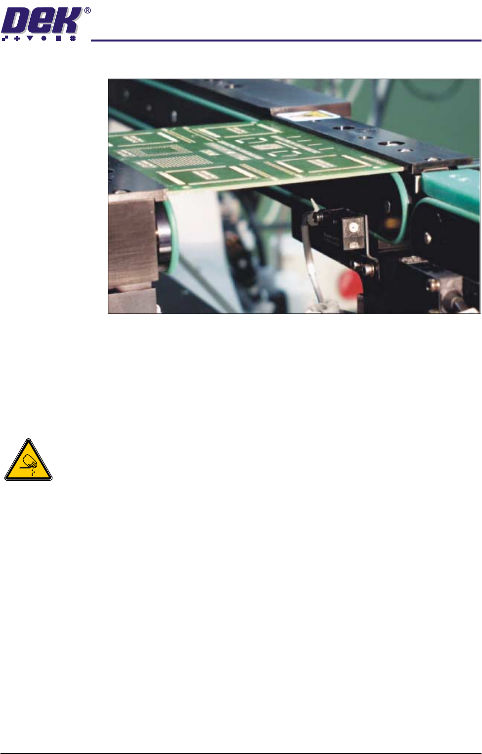
1. Place a board on the rails covering the sensor.
2. Turn the sensitivity control fully anti-clockwise, ensure that the LED is
extinguished.
3. Re-adjust the sensitivity control clockwise until the LED illuminates. Con-
tinue turning the sensitivity control clockwise for one more graduation.
4. Remove the board from the rails and confirm that the LED extinguishes.
Print Station Front Rail Parallelism
WARNING
BOARD CLAMPS. EXTREME CARE MUST BE EXERCISED WHEN WORKING IN
THE TOOLING AREA OF THE MACHINE TO AVOID INJURY. THE FOILS ON THE
FRONT AND REAR BOARD CLAMPS ARE VERY SHARP.
NOTE
Ensure Camera X Axis Parallelism (Camera and Vision Systems Module
Chapter of the Technical Reference Manual refers) has been carried out prior
to commencing the following procedure.
1. In Camera Diagnostics, home the Camera X and Y axes. Select Drive to
Board Stop Position the camera carriage is driven to the rear of the front
rail.
2. Raise the printhead and insert the head prop.
3. Select Close System to power down the machine.
4. Carry out either of the following:
a. Remove the camera from the camera mount and the camera mount from
the camera assembly bearing (refer to Camera and Vision Systems
Module Chapter of the Technical Reference Manual).
b. If available fit a spare camera assembly bearing to the right hand end of
the camera rail.
5. Fit a Dial Test Indicator (D.T.I.) to the camera assembly bearing.
TECHNICAL REFERENCE
ADJUSTMENTS & SETTINGS
1.30 High Throughput Conveyor Manual Chapter Issue 2 May 02
6. Using the D.T.I. check the front rail parallelism to camera carriage rail over
the length of the 'O' ring support plate to ±0.2mm.
7. If adjustment is necessary, using an Allen key, slacken the four rail securing
bolts and adjust the front rail as required. Tighten the bolts, re-check the
parallelism.
8. Remove the D.T.I.
9. Carry out either of the following:
a. Refit the camera mount and camera (see Camera and Vision Systems
Module Chapter of the Technical Reference Manual).
WARNING SHARP EDGE
PATENT No 5157438
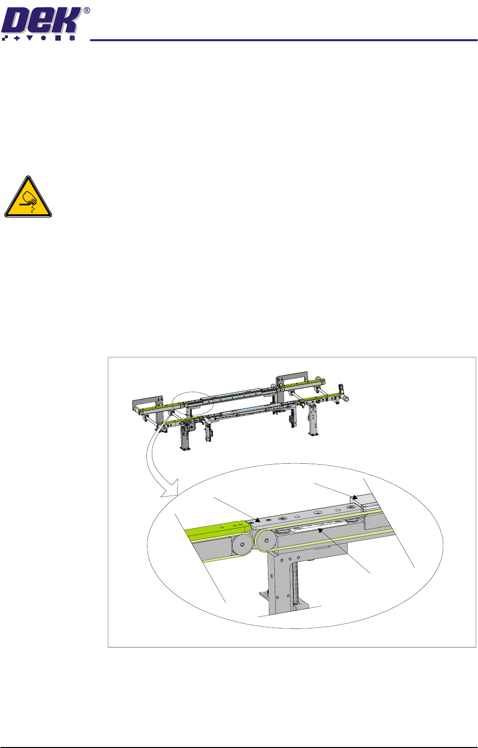
Print Station Rail Securing Bolts
TECHNICAL REFERENCE
ADJUSTMENTS & SETTINGS
Chapter Issue 2 May 02 High Throughput Conveyor Manual 1.31
b. Remove the spare camera bearing from the camera rail.
10. Switch on the machine, remove the head prop and lower the head. Initial-
ize, carry out the Home Position Rail Width Check and Camera Reference
Position (see Rail System Module Chapter and Camera and Vision Systems
Module Chapter of the Technical Reference Manual).
Print Station Rear Rail Parallelism
WARNING
BOARD CLAMPS. EXTREME CARE MUST BE EXERCISED WHEN WORKING IN
THE TOOLING AREA OF THE MACHINE TO AVOID INJURY. THE FOILS ON THE
FRONT AND REAR BOARD CLAMPS ARE VERY SHARP.
NOTE
Ensure Camera X Axis (Camera and Vision Systems Module Chapter of the
Technical Reference Manual refers) and Front Rail Parallelism has been carried
out prior to commencing the following procedure.
1. In Rail System Diagnostics, select Adjust and alter board width to 250mm.
2. Select Drive Rail to Board Width. The rails are driven to the board width
selected.
3. Locate all four mid rail tooling steps, two on each rail.
4. Using a suitable vernier calliper, at these points, check the rear rail to front
Mid Rail Tooling Step
Board Clamp
Mid Rail
View on Front Face of Print Station