3 Stage Conveyor.pdf - 第58页
TECH NICAL RE FERE NCE ADJUS TMEN TS & SETTI NGS 1.52 High Throughput Conveyor Manual Chapter Issue 2 May 02 configur ed as the print stat ion board stop . 23. Gain access to the M27 HTC Controller enclo sure. 24. Re…
TECHNICAL REFERENCE
ADJUSTMENTS & SETTINGS
Chapter Issue 2 May 02 High Throughput Conveyor Manual 1.51
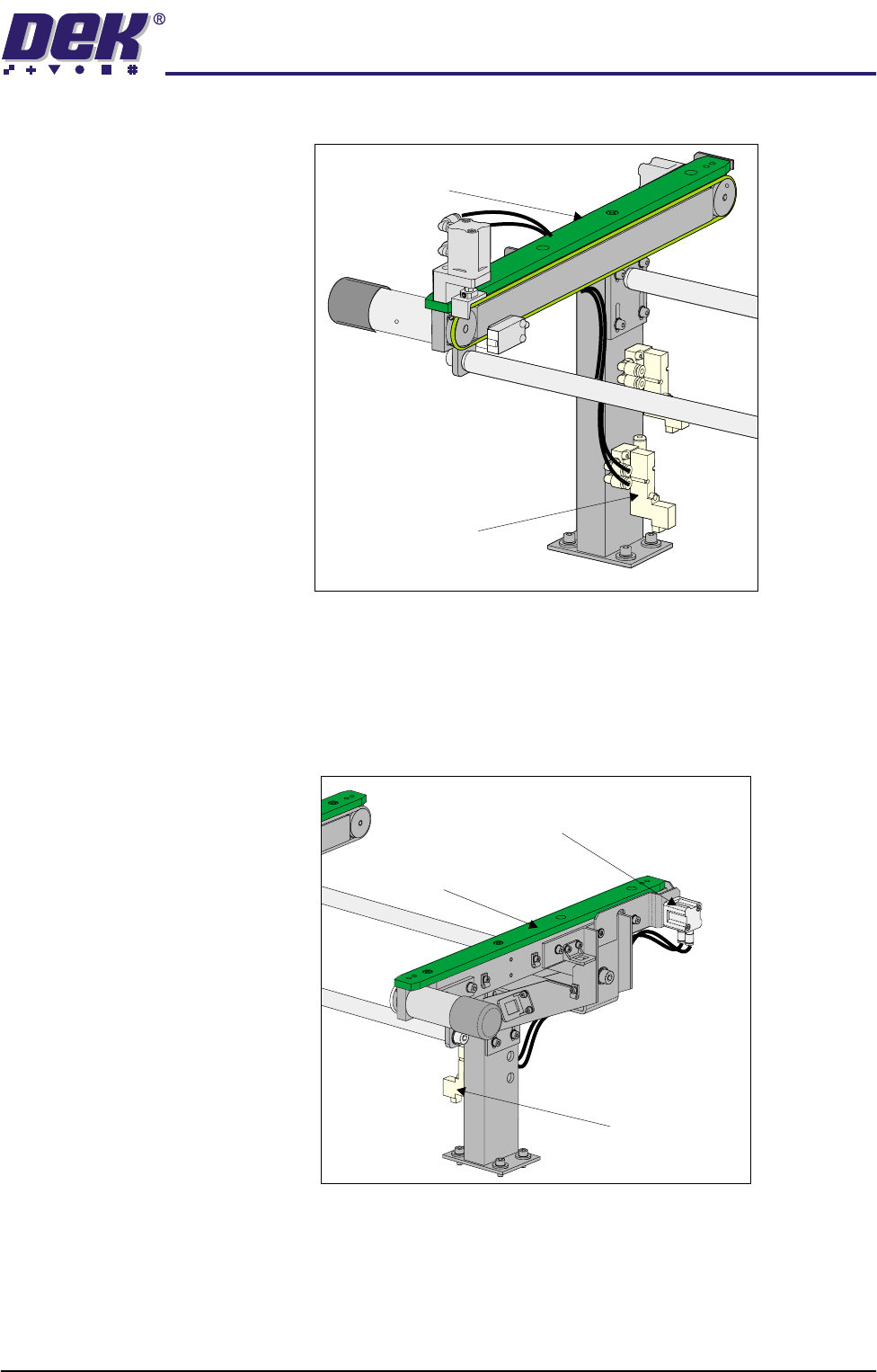
to the outboard end of the right hand auxiliary conveyor.
20. Disconnect and remove from the machine, the two pneumatic pipes from
solenoid (SOL 01) supplying print station conveyor board stop fitted to the
inboard end of the left hand conveyor.
21. Route the pneumatic pipes from solenoid (SOL 02) to the board stop, this
now configures the board stop from the print station board stop to the upline
board stop.
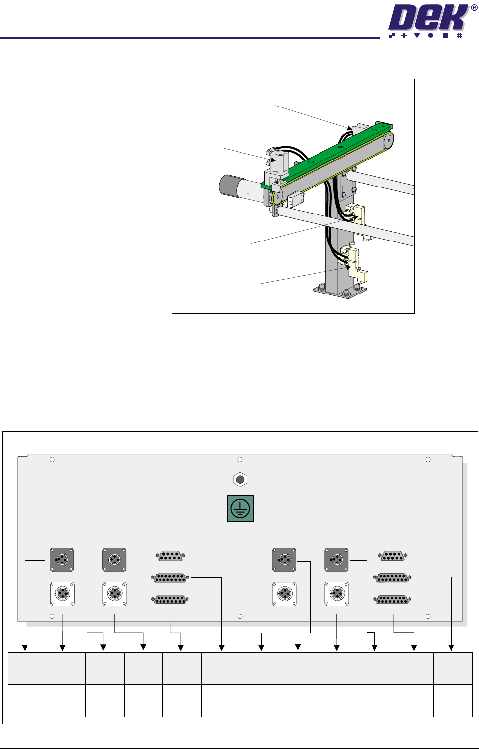
22. Fit two new 4mm pneumatic pipes to the solenoid (SOL 01) output ports A
& B and route the pipes to the to the upline conveyor board stop fitted to the
inboard end of the right hand auxiliary conveyor. The board stop now is
Right Hand
Auxiliary Conveyor
Pneumatic Solenoid
(SOL 03)
Left Hand
Auxiliary Conveyor
Pneumatic
Solenoid
(SOL 02)
Print Station Board Stop
Now Configured as Upline Board Stop
TECHNICAL REFERENCE
ADJUSTMENTS & SETTINGS
1.52 High Throughput Conveyor Manual Chapter Issue 2 May 02
configured as the print station board stop.
23. Gain access to the M27 HTC Controller enclosure.
24. Remove the four M27 enclosure securing screws.
25. Pull the M27 enclosure from its chassis mount and lower on the chassis
hinge to access the rear panel socket array.
26. To configure the M27 enclosure for left to right throughput direction, connect
the enclosure as shown in the graphic below:
27. On completion, refit the M27 enclosure.
Pneumatic Solenoid
(SOL 03)
Pneumatic Solenoid
(SOL 01)
Downline Conveyor
Board Stop
Upline Board Stop
Now Confgured as Print Station Board Stop
M27SK04 M27SK12M27SK18 M27SK19
M27SK08 (L/H)M27SK20 (L/H) M27SK08 (R/H)M27SK21 (R/H)
LANE A (LEFT) LANE A (RIGHT)
M27SK01 (L/H) M27SK01 (R/H)
M27SK02 (L/H) M27SK02 (R/H)
M27SK03 M27SK11
Inverted View on Rear of 3-Stage Conveyor Controller M27
M27SK20
(L/H)
M27PL20
(SOL 02)
N/C
N/C
N/C
M27PL08
(SOL 01)
M27PL21
(SOL 03)
M27PL04/
M27PL18
M27PL12/
M27PL19
M27PL01
(Loom
160622)
M27PL02
(Loom
160622)
M27PL02
(Loom
160645 or
160631)
M27PL01
(Loom
160643 or
160631)
M27SK04
M27SK08
(L/H)
M27SK18
M27SK01
(L/H)
M27SK02
(L/H)
M27SK12
M27SK21
(R/H)
M27SK19
M27SK08
(R/H)
M27SK01
(R/H)
M27SK02
(R/H)

TECHNICAL REFERENCE
ADJUSTMENTS & SETTINGS
Chapter Issue 2 May 02 High Throughput Conveyor Manual 1.53
28. Refit the external pneumatic connection to the external services panel.
29. Power up and initialize the machine. If required, remove the head prop and
lower the head.
30. In Set Prefs menu, ensure the Transport Mode option is selected to Left to
Right.