Specification_SIPLACE_F5_eng.pdf - 第34页
33 Description P P P Pl l l la a a ac c c ce e e em m m me e e en n n nt t t t R R R Re e e eli li li lia a a ab b b bili ili ili ilit t t ty y y y Aside from correct positi oning, placement reliabilit y also means a gen…
32
Description
Various factors contribute to the
placement accuracy of the
SIPLACE F
5
machine, e.g., the sta-
tionary PCB during the placement
process. As no accelerations are
acting on the placed components,
their position continues un-
changed. The PCB moves in and
out at a coordinated speed which
is automatically reduced just be-
fore the nominal position is
reached.
A further guarantee for long-term
high placement accuracy is the
position recognition of the axes of
the gantry and placement head by
means of optical scanning by in-
cremental encoders. Revolving
star and segments of the revolver
head are positioned by means of
high-resolution glass incremental
panels. The X- and Y-axes are posi-
tioned with the help of the metal
scales on each gantry axis.
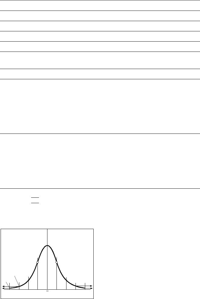
To determine the placement accu-
racy on SIPLACE machines, highly
precision glass components with
mounted structures are placed on
a dimensionally accurate glass
mapping plate. The results are sta-
tistically evaluated and presented
as a Gaussian standard distribu-
tion. In the case of the 12-nozzle-
revolver head the placement accu-
racy is ± 70 µm at a statistical reli-
ability of 4 sigma. In other words,
of one million placed components,
60 are outside the specified toler-
ance (= 60 dpm). If the accuracy
value ± 70 µm is divided by the
sigma value 4, the result is the
standard deviation S of 1 sigma =
± 17.5 µm.
A machine capability analysis is
conducted for each machine ac-
ceptance test.
Machine Criteria:
Placement Accuracy
Technical Data Gantry
Drive DC servomotors
Position measuring system (X/Y) Linear scales
Resolution of X-/Y-axis 2.5 µm
Speed of X-axis max. 2 m/s
Speed of Y-axis max. 2.5 m/s
Accuracy
X-/Y- and D-axis offset in optical component and PCB centering
6-nozzle revolver head
Angle accuracy
Placement accuracy
± 0.525° / 3 σ
± 0.70° / 4 σ
± 1.05° / 6 σ
± 67.5 µm/ 3 σ ( ± 45 µm/ 3 σ )*
± 90 µm/ 4 σ ( ± 60 µm/ 4 σ )*
± 135 µm/ 6 σ ( ± 90 µm/ 6 σ )*
Pick & Place-head
Angle accuracy
Placement accuracy
± 0.052° / 3 σ
± 0.07° / 4 σ
± 0.105° / 6 σ
± 37.5 µm/ 3 σ ( ± 30 µm/ 3 σ )**
± 50 µm/ 4 σ ( ± 40 µm/ 4 σ )**
± 75 µm/ 6 σ ( ± 60 µm/ 6 σ )**
* SIPLACE F
5
with DCA-package
** SIPLACE F
5
with Flip-Chip-vision module
Standard Deviation - dpm
-4
σ
-3
σ
-2
σσ
x
σ
2
σ
3
σ
4
σ
2700 dpm
60 dpm
P Point of Inflection
33
Description
P
PP
Pl
ll
la
aa
ac
cc
ce
ee
em
mm
me
ee
en
nn
nt
t t
t R
RR
Re
ee
eli
lili
lia
aa
ab
bb
bili
iliili
ilit
tt
ty
yy
y
Aside from correct positioning,
placement reliability also means a
gentle handling of the compo-
nents, so that these can be sol-
dered well later. Rework is mini-
mized or eliminated as a result.
On the SIPLACE F
5
among others
this is ensured through a number
of control functions, e.g., the vac-
uum checks and component vision
test during the revolver head se-
quence.
Unsuitable components are re-
jected, placed on the repair list and
automatically processed during a
repair cycle. An offset in the posi-
tion of the PCB relative to the con-
veyor system (PCB vision) and an
offset of the X-axis, Y-axis or rota-
tion of the component relative to
the midpoint of the nozzle (com-
ponent vision) trigger an immedi-
ate correction and thus placement
accuracy.
Thanks to the motionless PCB the
components remain in the exact
position they were placed. The
stationary component table pro-
tects, for example, the compo-
nents in Bulk Cases against dam-
age such as may occur due to
vibrations which are inevitable with
other placement concepts. Op-
tional add-on products ensure fur-
ther reliability: With the aid of the
component bar code scanner, the
correct placement program is
automatically sent to the station.
P
PP
Pi
ii
ic
cc
ck
kk
k-
--
-u
uu
up
p p
p e
ee
er
rr
rr
rr
ro
oo
or
rr
rs
ss
s
All errors which occur between the
time the component is picked up
and the time it is placed on the
PCB are pick-up errors. They in-
clude:
No component in the tape
Component cannot be removed
from the tape.
Vacuum error
Vision error due to faulty com-
ponent
Vision error due to unrecognized
component
P
PP
Pl
ll
la
aa
ac
cc
ce
ee
em
mm
me
ee
en
nn
nt
t t
t e
ee
er
rr
rr
rr
ro
oo
or
rr
rs
ss
s
Errors which occur after the com-
ponent has been placed on the
PCB. They include:
Rotation error
Too many components on PCB
X/Y-offset
P
PP
Pl
ll
la
aa
ac
cc
ce
ee
em
mm
me
ee
en
nn
nt
t t
t S
SS
Sp
pp
pe
ee
ee
ee
ed
dd
d
When used alone on the SIPLACE
F
5
the 6-nozzle revolver head
achieves a maximum placement
rate of 8,000 cph (components per
hour), the Pick & Place Head at
1,800 cph. These placement rates
can be verified on the demonstra-
tion PCB at Siemens.
Factors such as PCB size, number
of components per board and their
layout have a certain effect on the
speed in actual practice. The
placement speed in practice can
be predicted using a calculation
program.
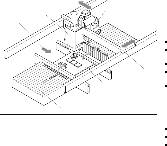
Machine Criteria:
Placement Reliability and Placement Speed
Placement Principle SIPLACE F
5
Pick & Place
Head
PCB Transport
Direction
Revolver Head
X/Y-Gantry
System
Fixed PCB
Fixed Component
Supply
34
Description
Despite the highly stable machine
frame, slight distortions of the
gentry axes cannot always be
avoided. With the aid of the map-
ping process the high placement
accuracy of the machine is pre-
served throughout its entire serv-
ice life.
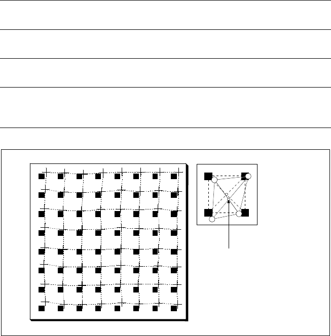
With this calibrating procedure,
which can be conducted quickly
and easily, the PCB camera recog-
nizes the fiducials on a mapping
calibration plate placed in its oper-
ating area. Any distortions are re-
vealed by comparing the nominal
grid on the glass plate with the ac-
tual grid “drawn” by placement
head. These distortions are taken
into account during all further posi-
tioning of X-/Y-axes and thus com-
pensated for.
Machine Criteria:
Mapping (Option)
Technical Data
Dimensions of the mapping
test plate
520 x 460 mm (for single conveyor)
520 x 215 mm (for dual conveyor)
Number of measurement
points
13 x 11 (standard resolution)
26 x 21 (high resolution)
Ambient temperature during
calibration + 20° ± 3°C
Components of the option
Test plate (special glass)
Calculation data (disk)
Case for secure storage
Nominal Grid of Mapping Plate and Actual Grid with
Deviations Due to Gantry
Corrected
Position