Specification_SIPLACE_F5_eng.pdf - 第4页
3 Description SIPLACE F 5 combines the Fine Pitch Pick & Place Head w ith the 6-nozzle-revolver head (Co llect & Place) to u nite high precision with high speed. Equipped with the 6-nozzle- revolver head SIPLACE …
2
SIPLACE F
5
with Waffle Pack Changer
Technical Data 42
Signal Interfaces
Connections
Dimensions and Set-Up Conditions
Component Forms 46
Nozzle Types: 51
Standard Range of Nozzle Types for 6-Nozzle Revolver Head
Standard Range of Nozzle Types for Pick & Place Head
Possible Machine Configuration 56
High Speed Placement of Large ICs, Flip Chips and Bare Dies
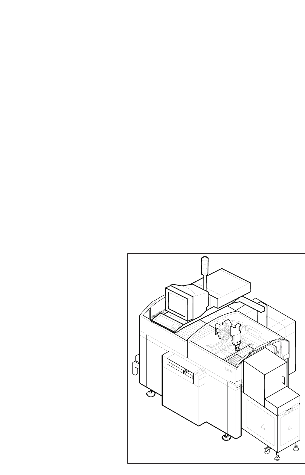
SIPLACE F
5

3
Description
SIPLACE F
5
combines the Fine
Pitch Pick & Place Head with the
6-nozzle-revolver head (Collect &
Place) to unite high precision with
high speed.
Equipped with the 6-nozzle-
revolver head SIPLACE F
5
place-
ment system optimally comple-
ments, SIPLACE S-23 HM. While
the PCB is still being moved, the
6-nozzle-revolver head is already
picking up the first components.
As soon as the PCB is clamped in
the conveyor, its exact position is
determined with the PCB vision
module. Afterwards the revolver
head picks up the remaining com-
ponents for the entire rotation
step and places its 6 components.
As soon as it is finished, the Pick
& Place Head begins picking up
and placing the components as-
signed to it.
For SIPLACE F
5
a DCA-package is
available, which contains an alter-
native DCA vision module
mounted in the 6-nozzle revolver
head instead of the standard vision
module. To optimize SIPLACE F
5
in
speed and accuracy for high speed
Flip Chip and bare die placement
the dynamic of the machine has
been changed.
The 6-nozzle-revolver-head greatly
increases the speed for products
with high percentages of ICs. The
ICs are placed on the PCB with the
speed of a Collect & Place Head
and with the required precision.
The principle of the stationary PCB
and the motionless component ta-
ble has decisive advantages:
Component tapes of all sizes
can be spliced, preventing ma-
chine stoppage due to empty
feeders.
The feeding of components
with no vibrating enables a reli-
able pick-up of even the small-
est components (e.g., 0402
chips).
Thanks to the flexible 12-nozzle
revolver heads - whose ideal
nozzle set-up is automatically
specified - the travel can be
minimized and the sequence of
placement optimally adjusted.
Holding the PCB stationary pre-
vents components from shifting
during placement.
Speed coupled with economic ef-
ficiency and set-up reliability is the
SIPLACE F
5
recipe for success.
The product range is rounded off
by optional additional products
such as component changeover
tables, tray changers, component
and PCB bar code scanners or
automatic nozzle changer.
Machine Description
Technical Data
Process Pick & Place / Collect & Place
Range of components
Standard Vision Module
DCA Vision Module
0603 to 55 x 55 mm
0.5 x 0.25 mm (0201*) to 55 x 55 mm
Benchmark placement rate
6-nozzle-revolver head
Pick & Place Head
8,000 cph
1,800 cph
6-nozzle-revolver head
Angle accuracy
Placement accuracy
± 0.225° / 3 σ, 0.30° / 4 σ, 0.45° / 6 σ
± 52.5 µm/ 3 σ, 70 µm/ 4 σ, 105 µm/ 6 σ
( ± 45 µm/ 3 σ, 60 µm/ 4 σ, 90 µm/ 6 σ )**
Pick & Place head
Angle accuracy
Placement accuracy
± 0.052° / 3 σ, 0.07° / 4 σ, 0.105° / 6 σ
± 37.5 µm/ 3 σ, 50 µm/ 4 σ, 75 µm/ 6 σ
( ± 30 µm/ 3 σ, 40 µm/ 4 σ, 60 µm/ 6 σ )***
PCB dimensions
50 x 50 mm to 460 x 460 mm
(optional 460 x 508 mm)
Feeder capacity 40 feeder locations
Component table
Types of Feeder modules
Changeover table, Waffle Pack Changer,
manual trays
Tapes, stick magazines, Bulk Cases
Operating system Microsoft Windows / RMOS
Connection In line or stand alone
Space required 4 m² / module
* SIPLACE F
5
is capable of handling 0201, if optional set up for it (Please contact Siemens).
** valid only with DCA-package
*** valid only with DCA-package and Flip Chip component vision module for Pick & Place head
4
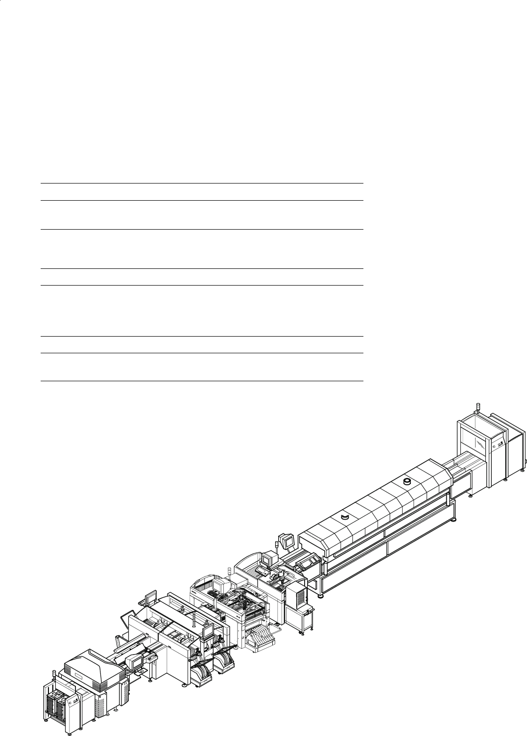
Input Station
Screen Printer
Oven
SIPLACE S-23 HM
SIPLACE HS-50
SIPLACE F
5
with Waffle Pack Changer
Output
Station
Example of a SIPLACE Placement Line
Description
The modular SIPLACE design is
characterized by flexibility and
adaptability. It permits an individual
production line composition of
similar and different modules.
When performance requirements
change the individual machines
can be recombined quickly
and without complications,
one of the major reasons
being their relatively
small size.
The SIPLACE family offers the
right product for each purpose -
from the super high-speed place-
ment system SIPLACE HS-50 to
the high-speed SMD placement
system SIPLACE S-23 HM and the
flexible Fine Pitch placement sys-
tem SIPLACE F
5
.
SIPLACE F
5
is ideally suited for
fixed set-up as well as for family
set-up with optimized changeover
times. When the required capacity
is low, however, it is also suitable
as a standalone placement sys-
tem.
Line Design
Technical Data
System SIPLACE SMD placement lines
Modules
SIPLACE HS-50 / SIPLACE S-23 HM /
SIPLACE F
5
Peripherals
Input/output station, screen printer,
solder oven, inspection conveyor etc.,
available from Siemens
Component range 0201* to 55 x 55 mm**
PCB conveyor
PCB dimensions
Ceramic substrate dimensions
Automatic width adjustment
50 x 50 mm to 460 x 460 mm
(optional 460 x 508 mm)
2" x 2" to 4" x 7"
Placement speed depends on layout of modules
Space required
4 m² / SIPLACE S & F modules
7.5 m² / SIPLACE HS module
* Collect & Place
** Pick & Place