Specification_SIPLACE_F5_eng.pdf - 第43页
42 1. After switching-on the station Technical Data: Signal Interfaces Signal Interface (20-Pin Ribbon C able Connector) to upstream station x3 to downstream stati on x4 Pin 13 GND 24 V Pin 10 Reserved Pin 14 Arrived Pin…
41
Description
SIPLACE placement machines are
high-tech systems whose speed,
placement accuracy and flexibility
are the result of the interaction of
hardware and software. During the
placement process all important
components in the machines are
monitored via software, machine
status data are recorded and ap-
propriately displayed to the ma-
chine operator. The SIPLACE diag-
nostic system is available as an
option in addition to this standard
functionality of SIPLACE. This
software tool which can be run on
the SIPLACE station computers
contains everything required for
the more detailed diagnosis of
SIPLACE placement systems:
information about SIPLACE
components
structure and strategy of
SIPLACE diagnosis
and all required notes regarding
possible dynamic system con-
trol states of SIPLACE.
The SIPLACE diagnostic system
thus provides the machine opera-
tor with a convenient tool which
offers further support during day-
to-day work in Production in addi-
tion to the SIPLACE system re-
ports.
The diagnosis is performed online
at the station computer in dialog
mode. The dialog is organized into
three main steps:
analysis of the machine event
location and derivation of the
cause
resolution of the problem
The queries to locate the cause are
made on the basis of a menu, i.e.,
the operator is privy to all possible
answers. At any time during the
dialog the machine operator can
access additional data such as
graphics or texts which furnish him
or her directions, hints and aids in
answering the questions posed by
the diagnostic system.
The procedure followed during this
dialog is specified by the system.
This ensures that the strategy of
minimum diagnostic effort imple-
mented in the diagnostic system is
followed. “Minimum diagnostic ef-
fort” means that causes which can
be ascertained easily or eliminated
quickly are examined first in order
to organize the search for causes
efficiently. This strategy is based
on the “SIEMENS Information
Bank” developed by SIPLACE ex-
perts.
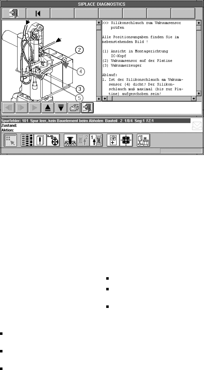
The cause discovered is presented
in the form of clearly phrased text.
The possible solutions for each
cause are displayed at the same
time as the cause. To facilitate un-
derstanding, the solutions are out-
put in the form of graphics with a
detailed description of the steps to
be taken. All required information
is stored in the diagnostic system
in the form of texts, scanned im-
ages or CAD graphics.
SIPLACE Software Architecture:
Diagnostic Tools (Option)
Analysis and On-Line-Support of SIPLACE Placement Systems
42
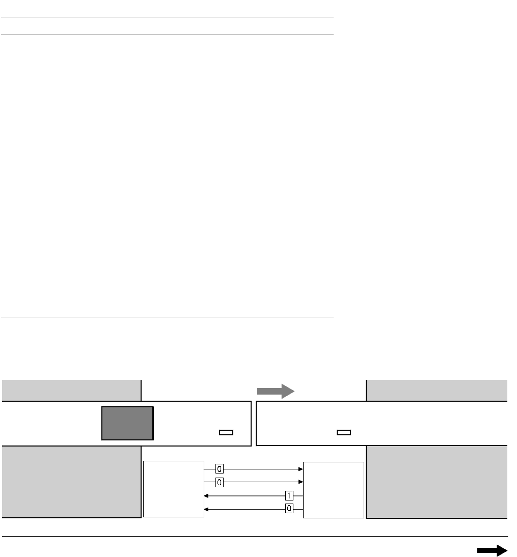
1. After switching-on the station
Technical Data:
Signal Interfaces
Signal Interface (20-Pin Ribbon Cable Connector)
to upstream station x3 to downstream station x4
Pin 13 GND 24 V Pin 10 Reserved
Pin 14 Arrived Pin 9 Reserved
Pin 15 Permission Pin 8 Reserved
Pin 19 Request Pin 4
+30 V DC
unsaturated
Pin 20
GND 24 V for request / re-
leased (contact separation)
Pin 5 GND 24 V
Pin 18 Released Pin 6 +24 V DC
Pin 12 Trouble signal loop Pin 11 Trouble signal loop
Pin 11 Pin 12
Pin 3 +24 V DC Pin 15 Permission
Pin 2 GND 24 V Pin 13
GND 24 V for per-
mission / arrived
(contact separation)
Pin 1 +30 V DC unsaturated Pin 14 Arrived
Pin 8 Reserved Pin 18 Released
Pin 9 Reserved Pin 19 Released
Pin 10 Reserved Pin 20 GND 24 V
Requirement
Delivery
Permission
Receival
Requirement
Delivery
Permission
Receival
Transport Direction
Conveyor Section 1
PCB
Sensor
PCB
Sensor
Conveyor Section 2
Station n
transports
PCB
to delivery
Station n+1
is ready to
receive PCBs
Conveyor 1 is On Conveyor 2 is Off
43
A detailed documentation of the
PCB transport signal interface is
available on request.
Technical Data:
Signal Interfaces
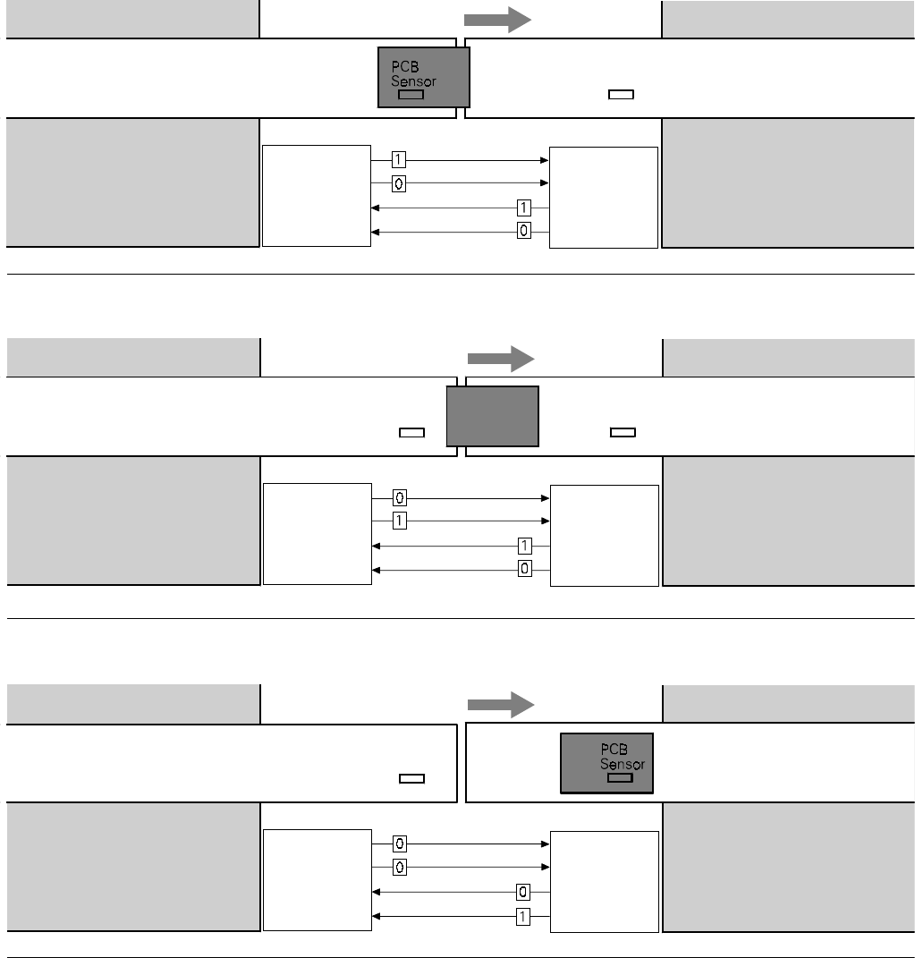
2. PCB handling has started
Conveyor 1 is On Conveyor 2 is On
Transport Direction
Conveyor Section 1
Conveyor Section 2
Station n
delivers PCB
to station n+1
Station n+1
waits for PCB
from station n
Requirement
Delivery
Permission
Receival
Requirement
Delivery
Permission
Receival
PCB
Sensor
Transport Direction
Conveyor Section 1
PCB
Sensor
Conveyor Section 2
Station n
has just
delivered PCB
Station n+1
waits for PCB from
station n, but has
not received it
Requirement
Delivery
Permission
Receival
Requirement
Delivery
Permission
Receival
PCB
Sensor
3. PCB is at delivery
Conveyor 1 is Off Conveyor 2 is On
Conveyor 1 is Off Conveyor 2 is On
Transport Direction
Conveyor Section 1
PCB
Sensor
Conveyor Section 2
Station n Station n+1
has just received
the PCB
Requirement
Delivery
Permission
Receival
Requirement
Delivery
Permission
Receival
4. PCB transport is finished