Specification_SIPLACE_F5_eng.pdf - 第6页
5 Description The main X-/Y-gantry features two placement heads , the 6 -nozzle high-speed revolver pl acement head and the high-precision P ick & Place Head . With certain overl apping, each placement head is spe ci…
4
Input Station
Screen Printer
Oven
SIPLACE S-23 HM
SIPLACE HS-50
SIPLACE F
5
with Waffle Pack Changer
Output
Station
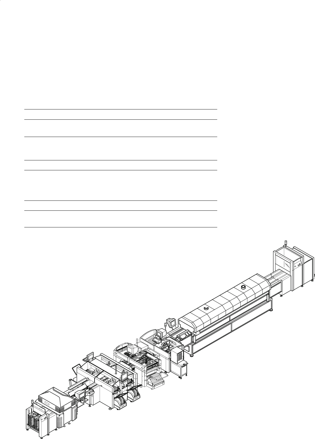
Example of a SIPLACE Placement Line
Description
The modular SIPLACE design is
characterized by flexibility and
adaptability. It permits an individual
production line composition of
similar and different modules.
When performance requirements
change the individual machines
can be recombined quickly
and without complications,
one of the major reasons
being their relatively
small size.
The SIPLACE family offers the
right product for each purpose -
from the super high-speed place-
ment system SIPLACE HS-50 to
the high-speed SMD placement
system SIPLACE S-23 HM and the
flexible Fine Pitch placement sys-
tem SIPLACE F
5
.
SIPLACE F
5
is ideally suited for
fixed set-up as well as for family
set-up with optimized changeover
times. When the required capacity
is low, however, it is also suitable
as a standalone placement sys-
tem.
Line Design
Technical Data
System SIPLACE SMD placement lines
Modules
SIPLACE HS-50 / SIPLACE S-23 HM /
SIPLACE F
5
Peripherals
Input/output station, screen printer,
solder oven, inspection conveyor etc.,
available from Siemens
Component range 0201* to 55 x 55 mm**
PCB conveyor
PCB dimensions
Ceramic substrate dimensions
Automatic width adjustment
50 x 50 mm to 460 x 460 mm
(optional 460 x 508 mm)
2" x 2" to 4" x 7"
Placement speed depends on layout of modules
Space required
4 m² / SIPLACE S & F modules
7.5 m² / SIPLACE HS module
* Collect & Place
** Pick & Place
5
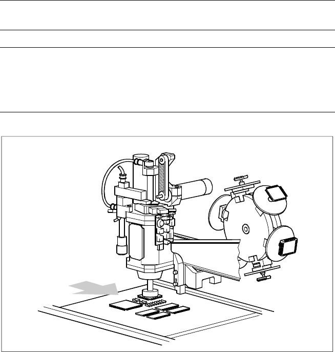
Description
The main X-/Y-gantry features two
placement heads, the 6 -nozzle
high-speed revolver placement
head and the high-precision Pick &
Place Head.
With certain overlapping, each
placement head is specialized for a
specific range of components.
Therefore it is possible to option-
ally distribute the components to
be placed between the two heads.
Placement Heads
Technical Data
Placement principle
Pick & Place Head
Collect & Place (Revolver ) Head
Components Entire SMD range
Component table:
Pick & Place head
6-nozzle revolver head
Feeder on changeover table;
Waffle Pack Changer or manual trays
Feeder on changeover table;
Waffle Pack Changer or manual trays
Placement Heads SIPLACE F
5
Pick & Place Head
Collect & Place Head
( Revolver )
PCB Transport
Direction
6
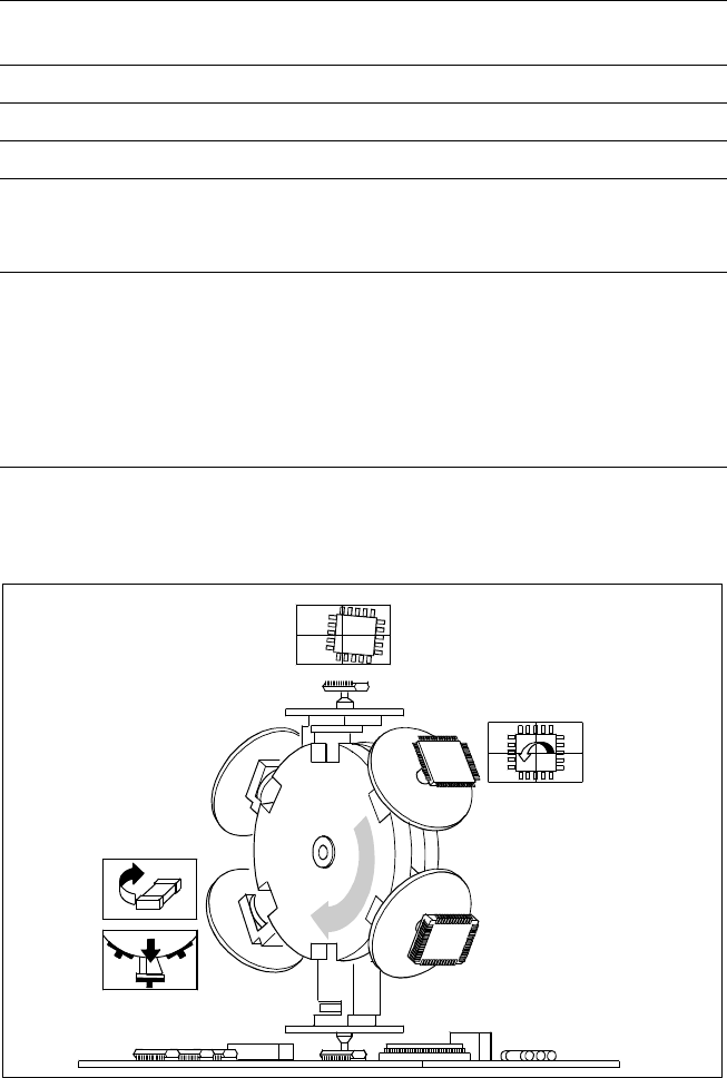
Description
SIPLACE F
5
combines the high-
precision Pick & Place head with
the 6-nozzle revolver head.
With the standard vision module
SIPLACE F
5
places ICs up to a size
of 32 mm accurately and rapidly. It
is therefore recommended for use
when there are large percentages
of ICs in the products to be manu-
factured. It greatly enhances per-
formance in the main application
range from PLCC 44 to QFP 208.
Equipped with the alternative DCA
vision module the 6-nozzle revolver
head handles components from
0.5 mm x 0.25 mm up to 13 mm x
13 mm. This vision module is part
of the DCA-package.
Equipped with the DCA-package
SIPLACE F
5
is optimized in speed
and accuracy for high speed Flip
Chip and bare die placement. Thus
the accuracy for the 6-nozzle re-
volver head with the alternative
DCA vision module achieves an
accuracy of ± 60 µm at 4 sigma
shown on a defined SIPLACE
demo board.
The cycle time of the 6-nozzle re-
volver head - and thus the real
achievable performance - depends
on the dimensions and the number
of leads / bumps of the compo-
nent.
Mechanically and electrically, the
6-nozzle revolver head is structur-
ally very similar to the 12-nozzle
revolver head. Nevertheless, the
two types of revolver heads can-
not be interchanged at will.
Placement Heads:
6-Nozzle Revolver Head for High-Speed IC Placement
6-Nozzle Revolver Head for High Speed Placement of large ICs, Flip
Chips and Bare Dies
Optical
Centering
Component
Turning
Component
Rejection
Segment-
Removal Point
Technical Data
Max. height*
max. weight*
8.5 mm
5 g
Stroke of Z-axis max. 16 mm
Programmable placement force 2.4 to 5.0 N
Benchmark placement rate 8,000 cph
Angle accuracy
± 0.225° / 3 σ
± 0.30° / 4 σ
± 0.45° / 6 σ
Placement accuracy
Standard vision module
DCA vision module
± 52.5 µm/ 3 σ
± 70 µm/ 4 σ
± 105 µm/ 6 σ
± 45 µm/ 3 σ**
± 60 µm/ 4 σ**
± 90 µm/ 6 σ **
* A uniformly reliable, speedy and accurate placement is guaranteed over the entire component
range up to this limit value. Beyond this, components can be placed if they satisfy specific basic
conditions (For other components please contact Siemens).
** Valid only with DCA-package