00193363-03.pdf - 第23页
Splice Detection Basic Package HS-50 2 Assembly inst ructions Splice Detection Basic Package SIPLACE HS-50 03/2008 Edition 23 : Replace the dist ance piece with t he moun t for the hub, then reinst all the hub an d conta…
2 Assembly instructions Splice Detection Basic Package SIPLACE HS-50 Splice Detection Basic Package HS-50
03/2008 Edition
22
2.7 Installing the splice detection hardware
2.7.1 Hub module
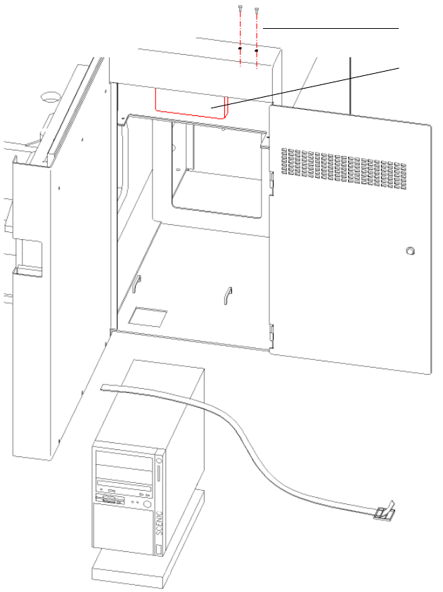
The hub is fitted beneath the side panel of the input conveyor (see Fig. 2.11 - 1). 2
2
Abb. 2.11 - 1 HUB module
2
: Loosen the screws for fixing the contact plug of the input flap (see Fig. 2.11 - 1).
2
2
Screws for
contact plug
HUB Unit
Splice Detection Basic Package HS-50 2 Assembly instructions Splice Detection Basic Package SIPLACE HS-50
03/2008 Edition
23
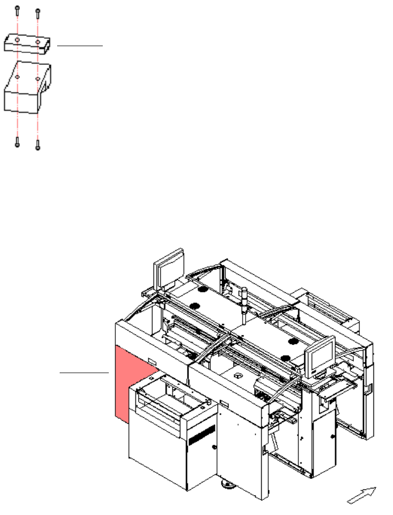
: Replace the distance piece with the mount for the hub, then reinstall the hub and contact plug.
2
Abb. 2.11 - 2 Distance piece
2
: Use the serial cable to connect the hub to the free COM port on the station computer.
2
Abb. 2.11 - 3 Distributor sector 4
2
: Detach the cover for the sector 4 distributor (see Fig. 16 - 3).
2
distance piece
sector 4
2 Assembly instructions Splice Detection Basic Package SIPLACE HS-50 Splice Detection Basic Package HS-50
03/2008 Edition
24
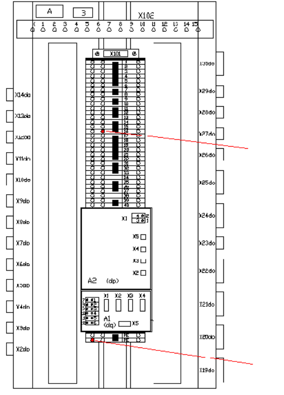
: Connect the power supply cable for the hub (00368322-01) to the main distributor. Connect
GND (white or blue) at X101-PE and 15 V (brown) at X101-16b (see Fig 2.11 - 4).
2
Abb. 2.11 - 4 Main distributor
2
2
2
2
2
2
2
2
+ 15 Volt
GND