00193363-03.pdf - 第25页
Splice Detection Basic Package HS-50 2 Assembly inst ructions Splice Detection Basic Package SIPLACE HS-50 03/2008 Edition 25 : Route the power sup ply cable correctly , a nd plug into the power sup ply socket for the hu…
2 Assembly instructions Splice Detection Basic Package SIPLACE HS-50 Splice Detection Basic Package HS-50
03/2008 Edition
24
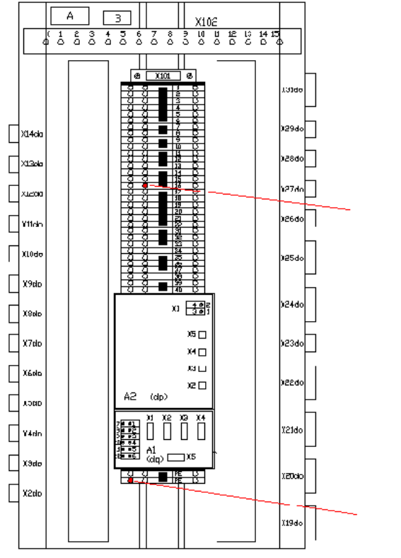
: Connect the power supply cable for the hub (00368322-01) to the main distributor. Connect
GND (white or blue) at X101-PE and 15 V (brown) at X101-16b (see Fig 2.11 - 4).
2
Abb. 2.11 - 4 Main distributor
2
2
2
2
2
2
2
2
+ 15 Volt
GND
Splice Detection Basic Package HS-50 2 Assembly instructions Splice Detection Basic Package SIPLACE HS-50
03/2008 Edition
25
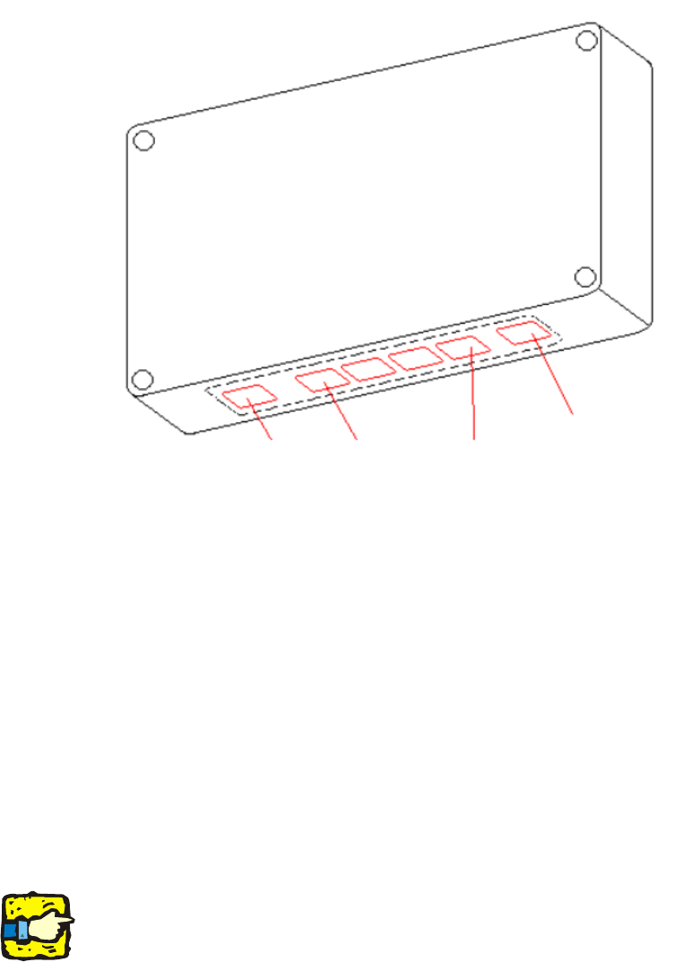
: Route the power supply cable correctly, and plug into the power supply socket for the hub (see
Fig. 16 - 5).
2
Abb. 2.11 - 5 Power supply socket
2
2.7.2 Connecting to the table controller (TC)
: Detach the covers from the sector 1, 2, 3 and 4 distributors.
: Replace the 4 covers with the new covers that allow the cables to be run from the hub to the
TC.
: Then fix the connecting cables:
– Long CAT 5 cables (item no. 00368249-01) to the covers of sector 2 and 3
– Short CAT 5 cables (item no. 00368250-01) to the covers of sector 1 and 4.
2
It is essential to start laying the cables from outside the panel. Do NOT start at the hub. 2
2
2
2
2
serial port
table 1 ... 4 power supply
2 Assembly instructions Splice Detection Basic Package SIPLACE HS-50 Splice Detection Basic Package HS-50
03/2008 Edition
26
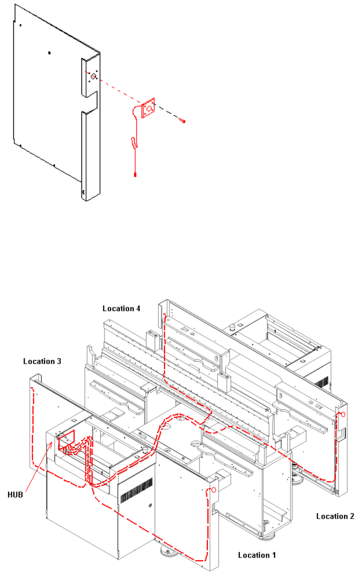
: To do this, pull the narrow end of the cable through the assembly hole in the cover, and fix the
wide plug using the enclosed oval head screw (see Fig. 16 - 6).
2
Abb. 2.12 - 6 Machine cover
: Then, starting from the panels, run the narrow ends of the cables through the machine to the
hub (see Fig. 16 - 7 and 16 - 8) using the pilot wire provided.
2
Abb. 2.12 - 7 Routing cables through the machine