SPS Configuration SX1 - 2-Version-4.pdf - 第10页
13.11.2018 Page 10 Configuration SPS for SX2/SX1 T o red uce the diversi ty of configura tions of the SPS magazin es, the follow ing variants have been be define d: 1. For the SX1 it is not po ssible to configure an SPS …
13.11.2018 Page 9
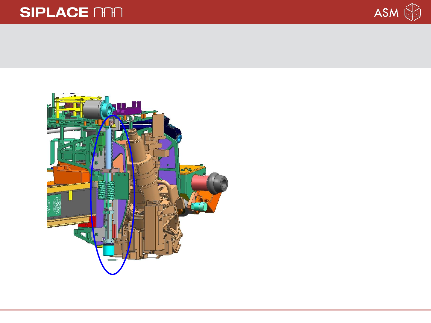
Configuration Smart Pin Support (SPS) on SX1/2
The SPS unit is mounted on the left side of the head holder on gantry 1.
User Manual SPS: 00197001-xx
Assembly Instruction SPS SX1/2: 00197002-xx
Note: The SX1 or SX 2 machine will
be equipped with one pin picker
only, independent of other machine
configuration!
13.11.2018 Page 10
Configuration SPS for SX2/SX1
To reduce the diversity of configurations of the SPS magazines, the following variants
have been be defined:
1. For the SX1 it is not possible to configure an SPS magazine on location 2, whether if
there a single- or dual conveyor.
2. For the SX2, only the SPS magazine Q10 on location 2 will be supported if a WPC
with two stationary cameras or 3D-coplan is mounted on location 1. The support
plate for location 2 is necessary.
3. The IC - Camera is not a precondition to use the Q10 magazine, but if no
IC camera installed, the Support plate 1 for location 1 is necessary.
4. If the L10 magazine installed, the Lock component reject box 03084467-xx have to
installed instead of the Component reject box up to 6x6 03062378-xx.
Attention: Headcrash, if installed the Component reject box up to 6x6!
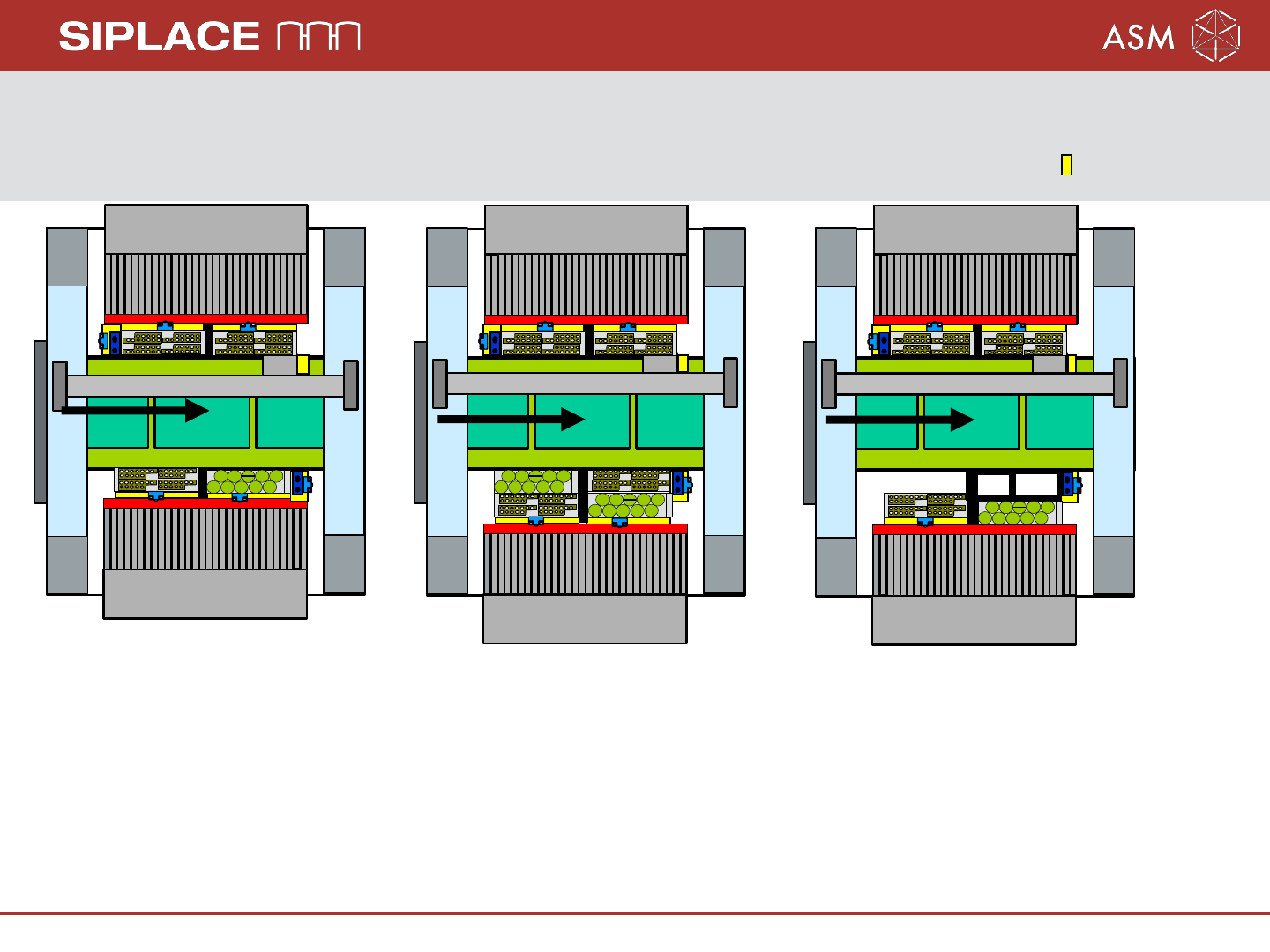
13.11.2018 Page 11
Configuration SPS for SX1
Gantry 1
Sensor
FCU
FCU
Sensor
Sensor
Sensor
Sensor
Sensor
Gantry 1
Sensor
FCU
FCU
Sensor
Sensor
Sensor
Sensor
Sensor
Gantry 1
FCU
FCU
Sensor
Sensor
Sensor
Sensor
Sensor
FC/3D
SST33
Location 1/2
Table position inner
SPS magazine L10 on
NC position 2
Location 1
Table position outer
SPS magazine L10 on
NC position 2 and/or L10
on NC position 3
Location 1
Table position outer
SPS magazine L10 on
NC position 2
Pin Picker