JO-116-001_w.pdf - 第111页
4-26 JO-1 16 1 105-001 2.1 Operation Procedure for [Measurement T ype 4] (4) When the feed er is c onnected to the jig, th e feede r commun ication is started and the parameters are read in. When this message is displaye…
4-25
JO-116
1105-001
2.1 Operation Procedure for [Measurement Type 4]
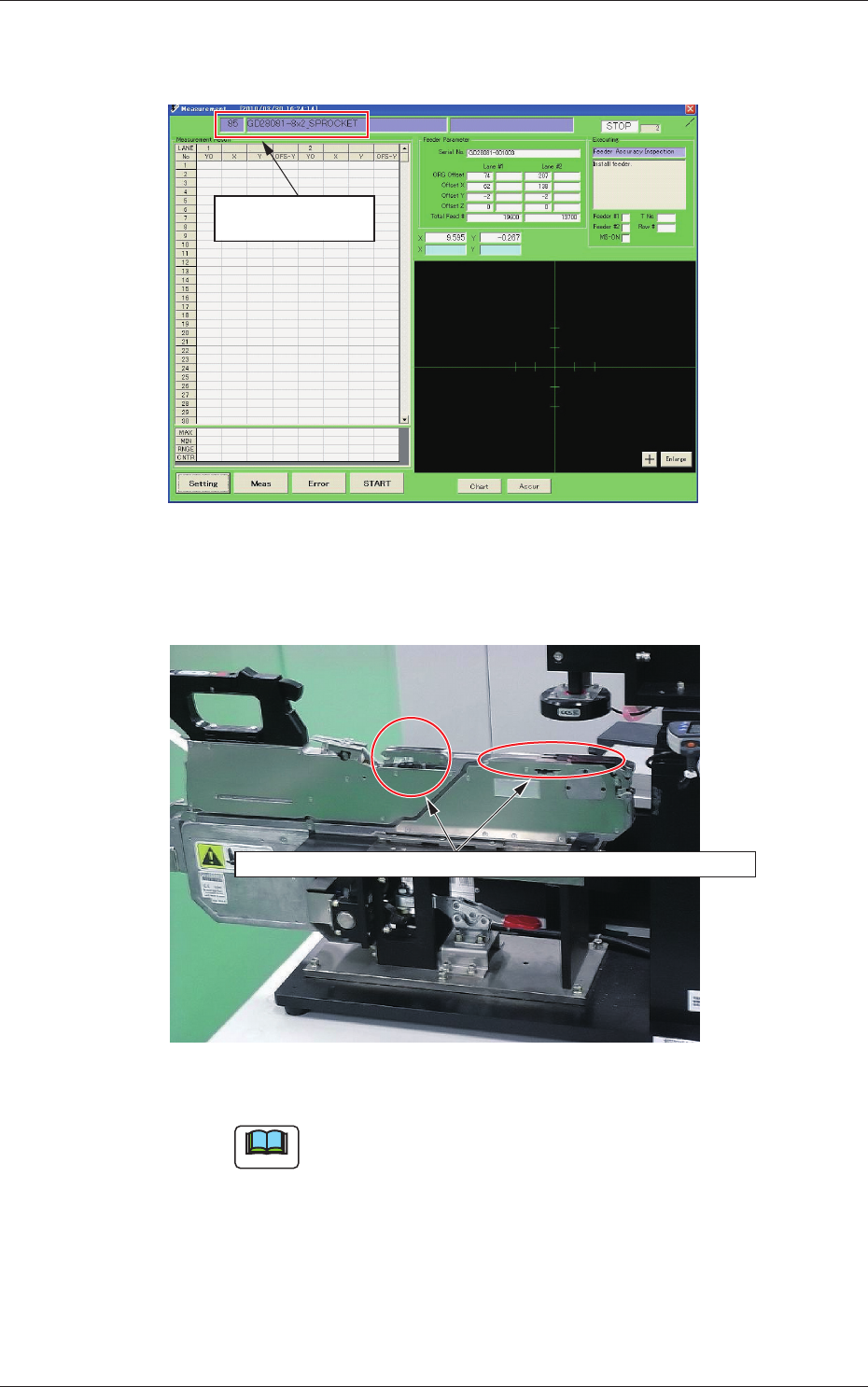
(2) Conrm the program type name displayed in the upper left in the
"Measurement" window.
Confirm the program
type name.
Fig. D28
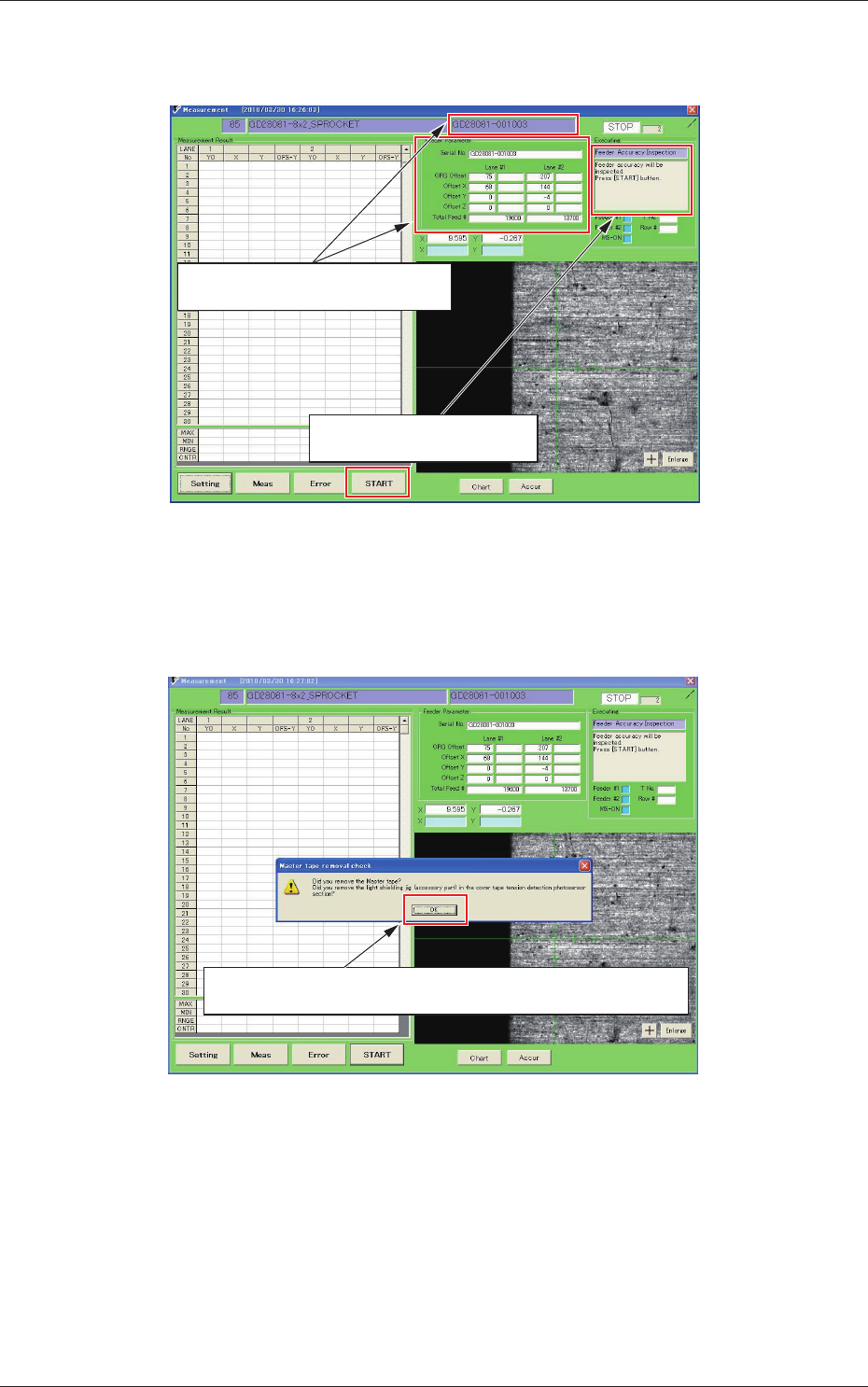
(3) Connect the feeder to the jig.
When the feeder is to be setup, remove the master tape and light shading jig.
Fig. D29
Note
In the adjustment operation for "Measurement Type 4" or
"Measurement Type 5", rst remove the tape and light shading
jig and then set the feeder.
4-26
JO-116
1105-001
2.1 Operation Procedure for [Measurement Type 4]
(4) When the feeder is connected to the jig, the feeder communication
is started and the parameters are read in.
When this message is displayed,
press the [START] button.
The feeder parameters are read and
displayed.
Fig. D30
(5) When the [START] button is pressed, the following conrmation
guide message is displayed.
When it is confirmed that the master tape and the light shading jig are
not set onto the feeder, click [OK].
Fig. D31
4-27
JO-116
1105-001
2.1 Operation Procedure for [Measurement Type 4]
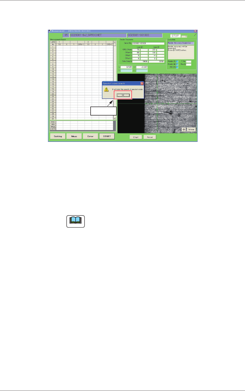
(6) When the conrmation guide message for the sprocket reference
positioning operation start, is displayed, click [OK].
Click [OK].
Fig. D32
After the communication with the feeder is started and the
parameter reading is performed, the feeder sprocket turns round
and the reference positioning operation is started up.
This operation is performed in the Lane 1 and Lane 2 in this
order.
Note
With the above procedure, the jig origin adjustment is ready.