JO-116-001_w.pdf - 第116页
4-31 JO-1 16 1 105-001 2.1 Operation Procedure for [Measurement T ype 4] (13) The following dialogue box window is displayed. When the offset data calculated based on the teaching data is to be changed, press the [Y es] …
4-30
JO-116
1105-001
2.1 Operation Procedure for [Measurement Type 4]
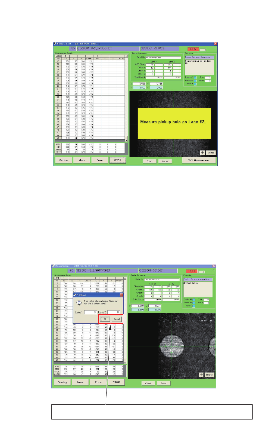
(10) Teach the Lane 2 pick-up hole teaching.
As above, teach all 45 hole positions as many as for one turn of
the sprocket.
Fig. D36
(11) When the teaching for all the pick-up holes for Lane 2 is
completed, each offset data calculation processing is started
based on the teaching results.
(The values displayed on the window are updated with a
mathematical operation).
(12) When each offset data calculation is completed, the direction Z
offset input window is displayed.
When the pick-up height data is not to be changed, press the [Cancel] button.
When the pick-up height data is to be changed, enter the offset value and press the [OK] button.
Fig. D37
4-31
JO-116
1105-001
2.1 Operation Procedure for [Measurement Type 4]
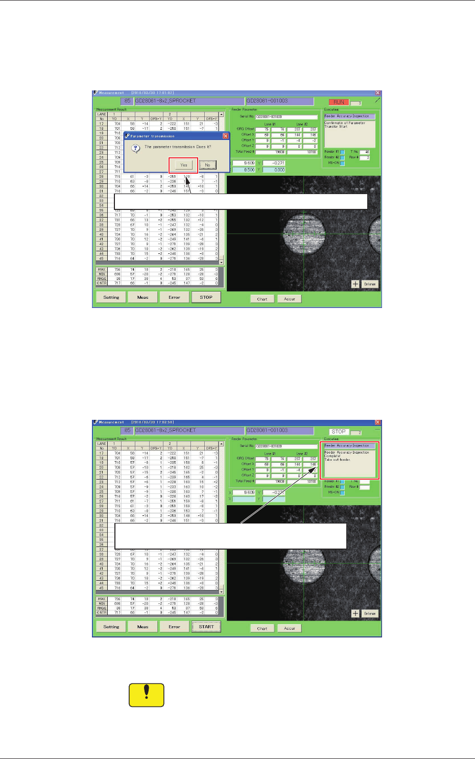
(13) The following dialogue box window is displayed.
When the offset data calculated based on the teaching data is to
be changed, press the [Yes] button. When it is not to be changed,
press the [No] button.
When the measurement results are written in the feeder, click [Yes].
Fig. D38
(14) When the transfer of the measurement results for writing them in
the feeder, is completed, and the following message "Take out the
feeder" is displayed, remove the feeder.
When the data transmission is completed and this message is
displayed, take out the feeder.
Fig. D39
Notice
During the data transfer to and writing in the feeder, do not
remove the feeder.
4-32
JO-116
1105-001
2.2 Operation Procedure for [Measurement Type 5]
2.2 Operation Procedure for [Measurement Type 5]
•
Lane Original Offset Adjustment and Recognition Mark Position
Adjustment
This operation is used to perform the complicated processing of the lane
origin offset adjustment and recognition mark position adjustment in a single
inspection, using the sprocket offset value set in the feeder.
When the jig origin teaching only is performed without disassembling or
replacement of driving gear section, adjust it using this [Measurement Type 5]
procedure.
Note
(a) In the automatic type change, this [Measurement Type 5] is selected
preferentially.
(b) This is the inspection type No. only for GT/GD-28081 or 28083.
As an example, the operation procedure in the case that the adjustment for
GD-28081 is performed using the [Measurement Type 5], is described.
Procedure
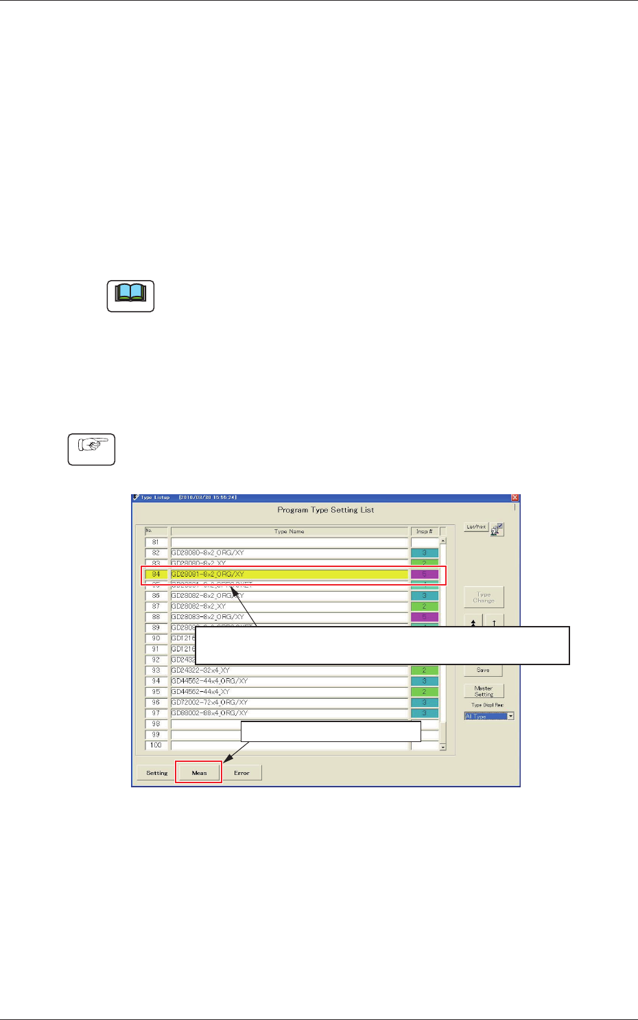
(1) Select the [Measurement Type 5] program for the corresponding
feeder model type, in the program type setup list.
(1) Select the type name “G D28081-8 × 2_ORG/XY”.
( The yellow-highlighted section shows the currently selected program.)
(2) Click the measurement button.
Fig. D40