JO-116-001_w.pdf - 第122页
4-37 JO-1 16 1 105-001 2.2 Operation Procedure for [Measurement T ype 5] (8) Perform the recognition mark position teaching. Fig. D47 (9) Perform the Lane 1 pick-up hole position teaching. (The positions of the 10 holes …
4-36
JO-116
1105-001
2.2 Operation Procedure for [Measurement Type 5]
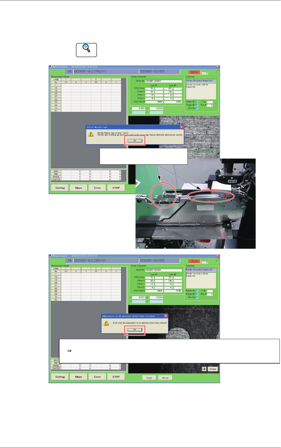
(7) When the sprocket reference positioning operation is completed,
the following operation guide message is displayed.
Then, attach the master tape and light shading jig correctly.
Reference
Refer to "2.3 Attachment and Detachment of Master Tapes" in
Section 4, for the attachment of the master tape.
Set the master tape and light shading
jig and click the [OK] button.
After that, the same adjustment operation procedure as for [Measurement Type 3] is performed.
Recognition mark position teaching, L1, L2 pick-up holes (every 10 perforations) teaching
When the attachment is completed, click the [OK] button.
Fig. D46
4-37
JO-116
1105-001
2.2 Operation Procedure for [Measurement Type 5]
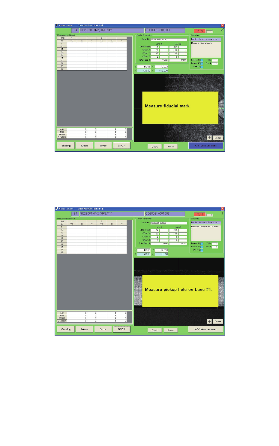
(8) Perform the recognition mark position teaching.
Fig. D47
(9) Perform the Lane 1 pick-up hole position teaching.
(The positions of the 10 holes are taught successively one by one.)
Fig. D48
4-38
JO-116
1105-001
2.2 Operation Procedure for [Measurement Type 5]
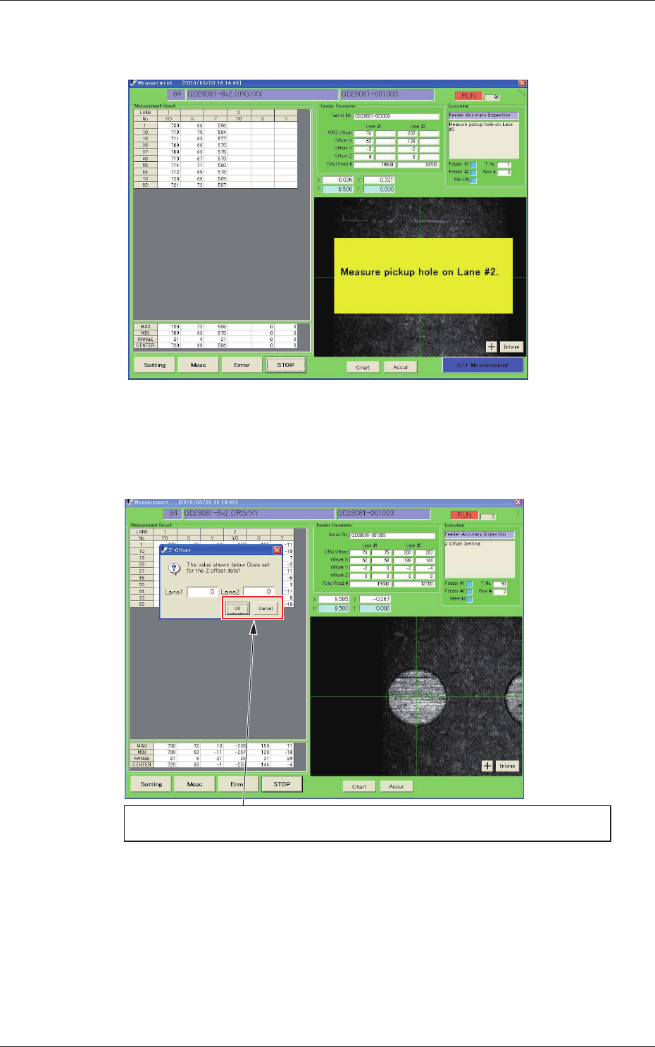
(10) Teach the Lane 2 pick-up hole teaching.
(The positions of the 10 holes are taught successively one by one.)
Fig. D49
(11) When each offset data calculation is completed, the direction Z
offset input window is displayed.
When the pick-up height data is not to be changed, press the [Cancel] button.
When the pick-up height data is to be changed, enter the offset value and press the [OK] button.
Fig. D50