JO-116-001_w.pdf - 第40页
2-3 JO-1 16 1 105-001 1.1 Cable Connection Schematic Cable Distribution LIGHT CN12 CN21 CN1 1 OUT 1 2 3 4 DC 9V X21 X12 X1 1 LIGHT LIGHT MUX10F 2Y MUX10F 1X PC CAMERA CAMERA X23 X22 X22 MONITOR X13 From 100-240V Keyboard…
2-2
JO-116
1.1 Cable Connection
1105-001
1.1 Cable Connection
Notice
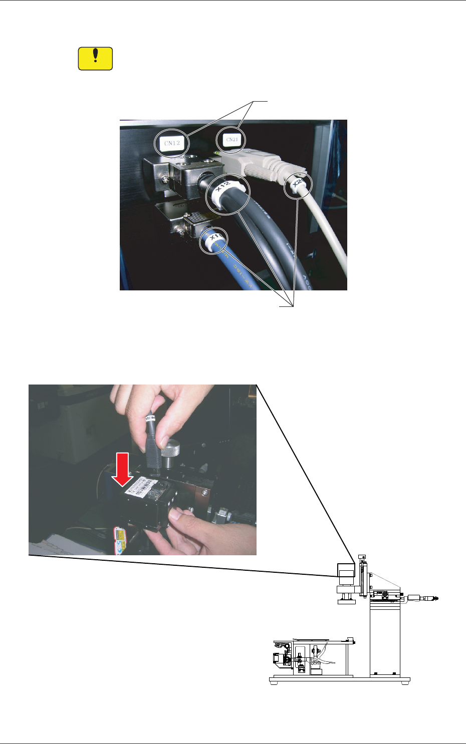
Check the seals on the device side and the cable ID plates. Both
IDs should match each other when the cables are connected.
Seals
ID Plates
Fig. B2
Fig. B3 Connection of Cables for Camera (used to capture the image of the pickup position)
2-3
JO-116
1105-001
1.1 Cable Connection
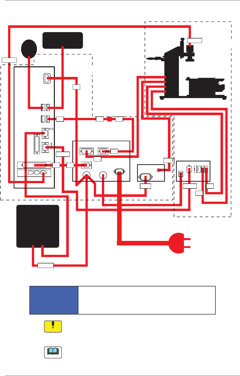
Schematic Cable Distribution
LIGHT
CN12 CN21
CN11
OUT
1 2 3 4
DC 9V
X21
X12
X11
LIGHT
LIGHT
MUX10F
2Y
MUX10F
1X
PC
CAMERA
CAMERA
X23
X22
X22
MONITOR
X13
From 100-240V
Keyboard
Mouse
Personal
Computer
Adjusting Jig
Electrical Box
Micrometer Unit
(Measured Data
Transfer Unit)
Liquid Crystal Display
Power Supply: 220 V AC
(Note)
Camera Control Unit
(Power Supply for
LED Illumination)
Inside of Box
Inside of Jig
Fig. B4
NOTICE
Before inserting the power plug, be sure to check
the voltage and conrm that it matches the specied
one. Otherwise, the jig unit may break down.
Notice
Cable "X23" must be connected only to the specied port of the
personal computer.
It must be connected to the above-indicated port.
Note
An IEC60320 (old IEC320) type power socket can be connected to the
power outlet.
2-4
JO-116
1105-001
1.2 Attachment of Micrometer
1.2 Attachment of Micrometer
NOTICE
•
Do not give a strong shock to the micrometer by
hitting against human body or an object.
Otherwise, the micrometer may be damaged,
resulting in inaccurate adjustment of the
component pickup position.
•
Tighten the setscrew until the micrometer can be
moved smoothly.
Excessive tightening may damage the
micrometer.
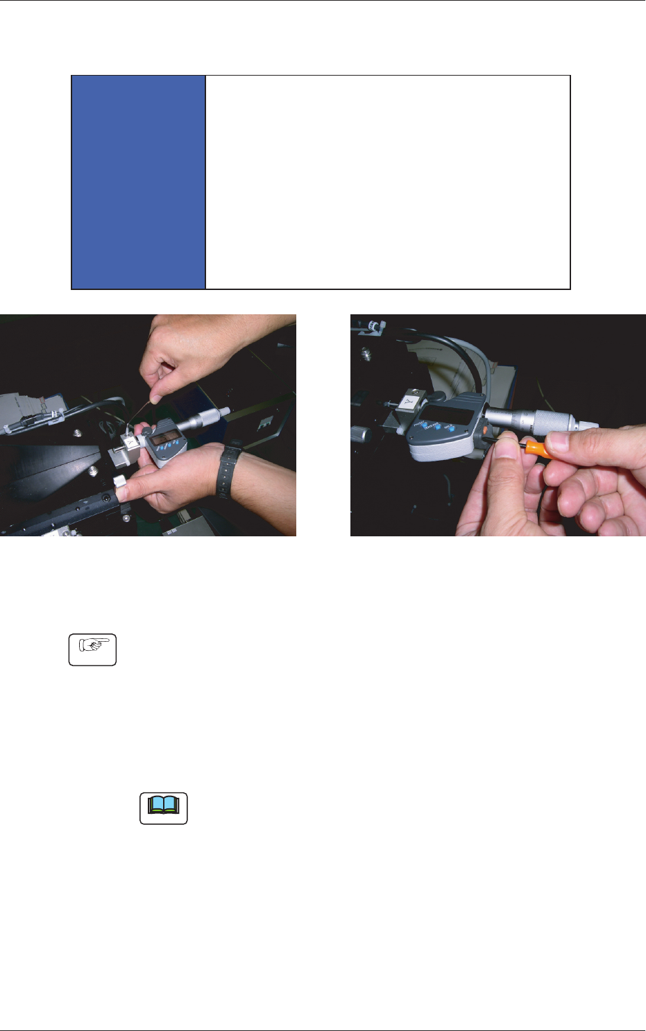
Attachment of Micrometer Connection of Micrometer Cable
Fig. B5 Attachment of Micrometer
Procedure
(1) Attach the micrometer to the measuring jig.
(2) Secure the micrometer with the setscrew.
(3) Connect the cable to the micrometer.
(4) Hold the end of the cable with your ngers and tightn the screw
so that no clearance can be left between the cable and the
micrometer.
Note
After the attachment is completed, check how the micrometer works.