JO-116-001_w.pdf - 第68页
3-19 JO-1 16 1 105-001 5. "System Setting" Window (2) Outline of Each System Data Control Mode The set data is used to change the control mode. "0" or "1" can be set. 0: Through Mode (Operat…
3-18
JO-116
1105-001
5. "System Setting" Window
5. "System Setting" Window
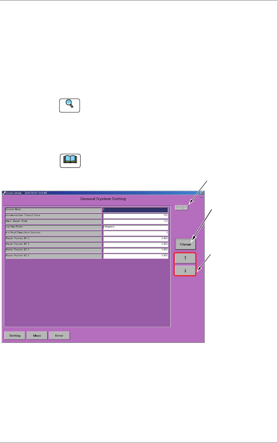
In the "System Setting" window, the set value peculiar to the machine can be
dened
(1) How to open the "System Setting" window
Only "Administrator" can open the "System Setting" window and
change the settings.
Change the current authority level to "Administrator".
Reference
Refer to "1. Administrative Authority Change" in "Section 3" for
how to change the authority.
Make the subcursor appear in the "Type Listup" window and press the
[Setting] button.
Note
The subcursor can be located at any place regardless of whether the
type data is already registered or not.
Used to print the
system data.
Used to move
the cursor.
The entry window
for the pertinent set
value opens,
enabling you to change
the set value.
Fig. C14 "System Setting" Window

3-19
JO-116
1105-001
5. "System Setting" Window
(2) Outline of Each System Data
Control Mode
The set data is used to change the control mode.
"0" or "1" can be set.
0:
Through Mode
(Operator Conrmation Omitted at Accuracy Inspection)
1:
Step Mode
(Operator Conrmation Displayed
Communication Timeout Value
Specify the time at which the "Communication Impossible" mode
should be detected in the RS232C serial communication.
Unit:
seconds
Alarm Buzzer Mode
Specify the period of time during which the buzzer should sound when
an error has occurred.
When "0" is set, the buzzer keeps on sounding until it is stopped with
the buzzer button.
"0" or "0.1 to 600.0 seconds (10 minutes)" can be set.
Log Data Folder
Specify the folder in which the inspection data log le should be saved.
Up to 62 characters can be used for the registration.
# of Feed Times from Sprocket
Specify the number of master tape idle feeding times required at the
start of the inspection.
A value "0 to 10" can be set.
Master Position #1 X and Y/Master Position #2 X and Y
The set parameters represent the inspection positions of the master
feeder.
3-20
JO-116
1105-001
6. "Measurement" Window
6. "Measurement" Window
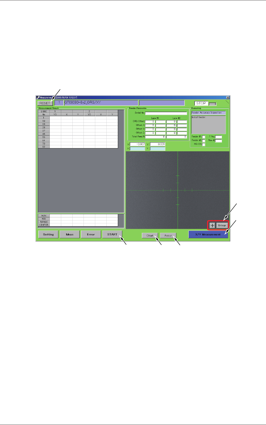
This window can be used to execute an accurate inspection of the feeder,
view the results of the inspection, and create an accuracy table.
When you press the [Meas] button located at the bottom of each window, the
"Measurement" window opens.
Description of Each Button
[5]
[6]
[3]
[4][1]
[2]
Fig. C15 "Measurement" Window
[1] [START] button
When pressed, this button starts the measurement.
While the measurement is performed, the label on the button is changed
to "STOP". When the [STOP] button is pressed, the measurement is
interrupted temporarily.
[2] [RESET] button
This represents that the measurement is interrupted. This appears when
the measurement is interrupted temporarily with the [STOP] button in
[1].
[3] [Accur] button
When pressed, this button opens the "Accuracy Measurement Table"
window.