00191498-01.pdf - 第25页
Conversion Instructions S-20/S-23 HM/F4/F5 Power supply 09/99 edition 25 3 T ools an d equip ment – Set of DIN 9 1 1 Allen key s – Set of sl otted-hea d screwdr ivers – Multimet er 4P a r t s 1 10/2 08 V conversion kit f…

Power supply Conversion Instructions S-20/S-23 HM/F4/F5
2 Safety instructions 09/99 edition
24
2 Safety instructions
DANGER OF DEATH
This retrofit must be carried out by SIEMENS engineers or appropriately qualified personnel. 2
Å Always follow the accident prevention regulations applicable in your country, e.g. EN 60204.
Å End all operations on the placement system.
Å Shut down the Windows NT operating system correctly, otherwise you may experience prob-
lems when restarting the placement system or you could loose data.
Å Switch the placement system off at the main switch.
Å Disconnect the placement system from the power supply.
Å Secure the placement system to prevent reclosing and put up a sign to indicate that servicing
work is in progress (see chapter 2 Operational Safety of the operating instructions).
S-20/F
4
/F
5
S-23 HM
Component table
or component
table, movable
Transformer T1
237 VAC/50 Hz
230 VAC/50 Hz
223 VAC/50 Hz
122 VAC/60 Hz
115 VAC/60 Hz
108 VAC/60 Hz
Fuse F1
3.15 A MT at
237 VAC/230 VAC/223 VAC
6.3 A T at
122 VAC/115 VAC/108 VAC
Adhesive label
3.15 A MT at
237 VAC/230 VAC/223 VAC
6.3 A T at
122 VAC/115 VAC/108 VAC
WPC 80F3
Power supply unit
00320064-03 or
later
Transformer T1
3 x 400 VAC/50 Hz
(star connection)
3 x 230 VAC/60 Hz
(delta connection)
Placement
system
Assembly Subassembly Ratings

Conversion Instructions S-20/S-23 HM/F4/F5 Power supply
09/99 edition
25
3 Tools and equipment
– Set of DIN 911 Allen keys
– Set of slotted-head screwdrivers
– Multimeter
4Parts
110/208 V conversion kit for Siplace S-20/F4, item no. 00117185-01, consisting of: 4
– Fuse-link 5x20, 6.3 A slow-blowing, 10x (for component table)
– USA plug-in adapter, X1, item no. 00310731-01 (for service socket)
– Single wire, 2.5 mm², yellow-green, H07V-K, 2x
(jumpers BR3 and BR4 are set for the 4-conductor power connection, PE and N conductors on
the right-hand terminal panel)
– Single wire, 1.5 mm², black (jumper for ∆-connection of WPC)
– Circuit diagram, 110/208 V conversion kit for SIPLACE S-20/S-23 HM/F
4
/F
5
,
drawing no. 00117185-010101LD3, 3 pages (see appendix, page 19 onwards)
– Power supply unit conversion instructions for Siplace S-20/S-23 HM/F
4
/F
5
,
item no. 00191498-01, 09/1999 edition, German and English
5 Converting placement systems from 3x400VAC to
3x208VAC
PLEASE NOTE: 5
Uncouple the two component tables before switching off the placement system.
The wafflepack changer can be left coupled while the placement system is converted. 5
DANGER OF DEATH 5
Å Shut down the placement system correctly as described in section 2.
Å Disconnect the placement system from the mains supply.
Power supply Conversion Instructions S-20/S-23 HM/F4/F5
5 Converting placement systems from 3x400VAC to 3x208VAC 09/99 edition
26
Å Take suitable steps to ensure that the placement system cannot be reconnected to the power
supply while the conversion work is being carried out.
Å Put up warning signs to indicate that work is being carried out on the electrical system.
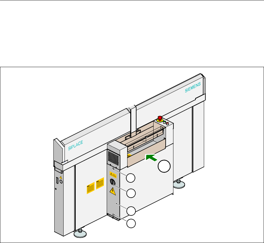
5.1 Dismantling the power supply unit
Å Loosen the two hexagon socket-head screws (item 2 in Fig. 5 - 1).
Å Remove the cover (item 3 in Fig. 5 - 1).
Fig. 5 - 1 Removing the cover over the power supply unit
(1) Main switch
(2) Hexagon socket-head screw, 2x
(3) Cover
(T) PCB transport direction 5
Å Loosen the hexagon socket-head screw at the bottom of the power supply unit.
Å Use the handle to pull the power supply unit out of the housing.
The terminals of transformer T1 and T2 and the inrush current limiter are now accessible for
rewiring.
1
2
T
4
0
0
V
4
0
0
V
3
2