00191498-01.pdf - 第28页
Power supply Conversion Instructions S-20/S-23 HM/F4/F5 5 Converting placement systems from 3 x 400 VAC to 3 x 208 VAC 09/99 edition 28 5.2 Converting the single-phase t ransformer T1 from 230 V AC to 1 10 V AC Å Disconn…
Conversion Instructions S-20/S-23 HM/F4/F5 Power supply
09/99 edition
27
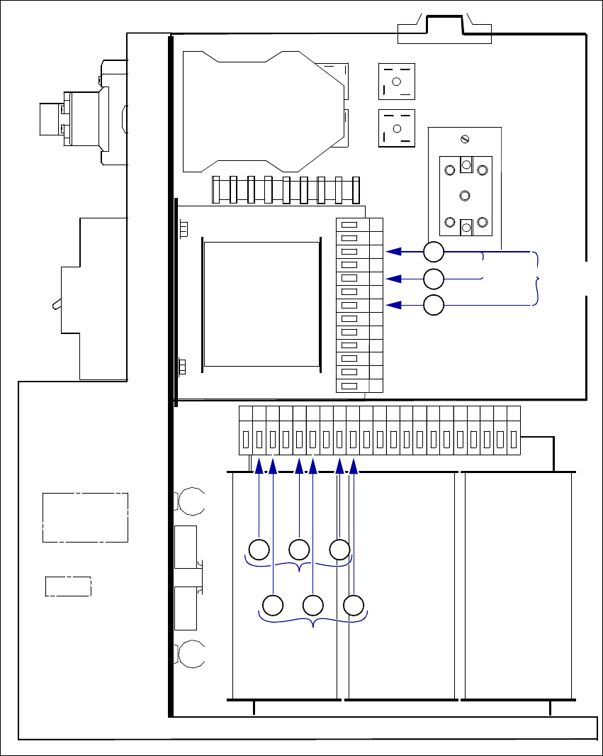
Fig. 5 - 2 Terminals for transformer T1 and T2 and the inrush current limiter
(T1) Single-phase transformer T1 (2) - (6) 230 VAC
(2) - (4) 110 VAC
(T2) Three-phase transformer T2 (1), (2), (3) 3 x 400 VAC
(7), (8), (9) 3 x 208 VAC
(A1) Inrush current limiter 5
V
1
~~
+-
~
V
5
V
4
~
~
+
-
~
~
+
-
~
-
V
3
V
2
A
B
230
230
150
120
N
+5%
P
E
-5%
24
8
0
8
24
N 208 400 400 208 400 400208 400 400 SC 69 48
42
0V69 69 48 48
42 42
6
4
2
7
1
8
2
9
3
A1
Inrush current limiter
T1
Single-phase
transformer
T2
Three-phase
transformer
230VAC
110VAC
3x400VAC
3x208 VAC

Power supply Conversion Instructions S-20/S-23 HM/F4/F5
5 Converting placement systems from 3x400VAC to 3x208VAC 09/99 edition
28
5.2 Converting the single-phase transformer T1 from 230 VAC to 110 VAC
Å Disconnect the black wire from terminal 6 (230 V) and connect it to terminal 4 (120 V - see Fig.
5 - 2).
5.3 Converting the three-phase transformer T2 from 3 x 400 VAC to 3 x 208 VAC
Å Disconnect the black wire from terminal 1 (400 V) and connect it to terminal 7 (208 V) (see Fig.
5 - 2).
Å Disconnect the black wire from terminal 2 (400 V) and connect it to terminal 8 (208 V) (see Fig.
5 - 2).
Å Disconnect the black wire from terminal 3 (400 V) and connect it to terminal 9 (208 V) (see Fig.
5 - 2).
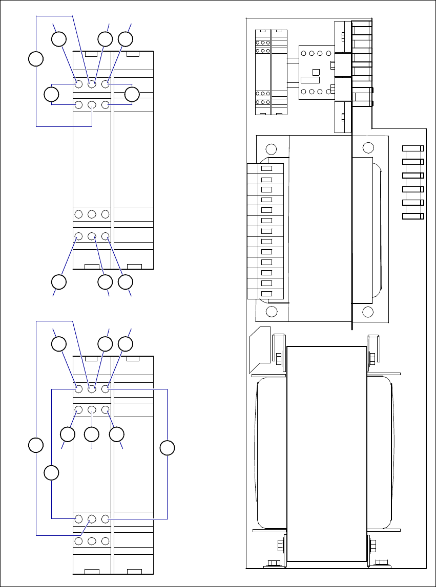
5.4 Converting the inrush current limiter A1 from 3x400 VAC to 3x208 VAC
Å Disconnect wire 3 from terminal 13 and connect it to terminal 14 (see Fig. 5 - 3).
Å Disconnect wire 6 from terminal 23 and connect it to terminal 24 (see Fig. 5 - 3).
Å Disconnect wire 9 from terminal 33 and connect it to terminal 34 (see Fig. 5 - 3).
Å Disconnect wire 2 from terminal 12 and connect it to terminal 13 (see Fig. 5 - 3).
Å Disconnect wire 5 from terminal 22 and connect it to terminal 23 (see Fig. 5 - 3).
Å Disconnect wire 8 from terminal 32 and connect it to terminal 33 (see Fig. 5 - 3).
5.5 Installing the power supply unit
Å Carefully push the power supply unit into the housing until it reaches the stop.
Å Secure the unit to the bottom part using the hexagon socket-head screw.
Å Check that the yellow-green protective earth conductor is connected to the cover.
Å Attach the cover.
PLEASE NOTE: 5
Make sure that the actuating shaft of the main switch slides easily into the opening in the ro-
tary button. 5
Å Fix the cover in place using the two hexagon socket-head screws.
Conversion Instructions S-20/S-23 HM/F4/F5 Power supply
09/99 edition
29
Fig. 5 - 3 Front panel of the power supply unit - connecting the inrush current limiter (003429988-01)
(1) - (9) Numbers of the connecting wires
(A1) Inrush current limiter 5
12 22
14 24 34
32
230
230
150
120
N
+5%
P
E
-5%
24
8
0
8
24
A1
1 L1 3 L2 5 L3 21 NC
SIEMENS
01
2 T1 4 T2 6 T3 22 NC
V1
V4
V5
V3
11 21 31
13 23 33
A1
12 22 32
14 24 34
11
21
31
13 23 33
1
7
4
2 8
5
3
9
6
A1
12 22 32
14 24 34
11
21
31
13 23 33
1
7
4
2
5
8
63 9
T2
Three-phase
transformer
T1
Single-phase
transformer
3x208VAC
3x400VAC