00191498-01.pdf - 第31页
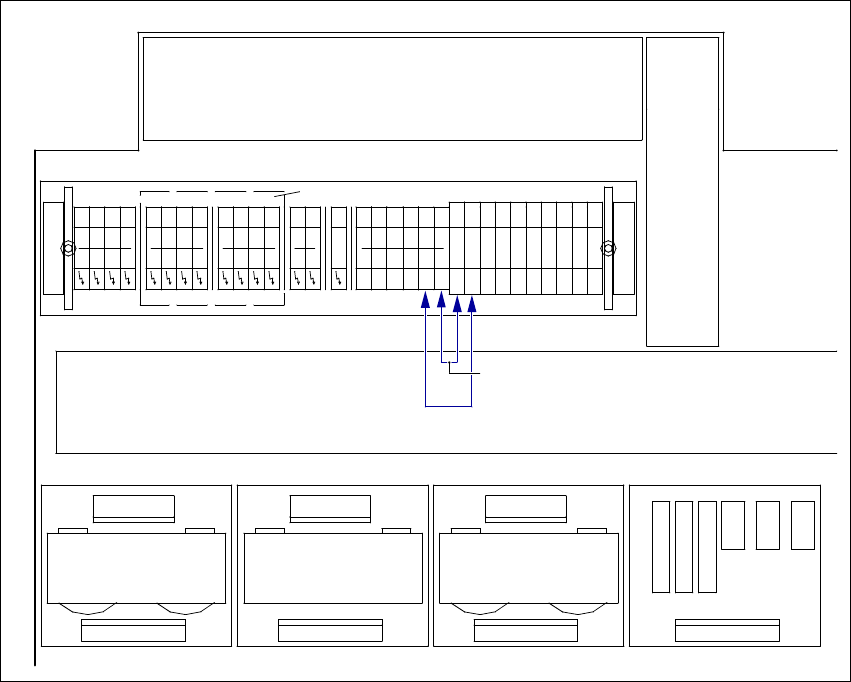
Conversion Instructions S-20/S-23 HM/F4/F5 Power supply 09/99 edition 31 Fig. 6 - 1 T erminal panel, right -hand side, terminal strip X206 X X D A5 A4 A3 PE X X X1rd X2rd X2rc L2 L3 X206 6 A2 X X1rc X1rb X2re X N N N N N…

Power supply Conversion Instructions S-20/S-23 HM/F4/F5
6 4 or 5-conductor connection for the mains supply 09/99 edition
30
6 4 or 5-conductor connection for the mains supply
The connections consist of either 4 or 5-conductor cables, as specified by the electricity company.6
4-conductor connection 6
For the 4-conductor connection, the neutral (N) and protective earth (PE) conductors are com-
bined in a common wire PEN. 6
Å Insert the yellow-green wires BR3 and BR4 between the N and PE terminals in the right-hand
terminal panel of terminal strip X206 (see Fig. 6 - 1).
5-conductor connection 6
For the 5-conductor connection, the neutral (N) and protective earth (PE) conductors run in sep-
arate wires. 6
Å Remove the yellow-green wires BR3 and BR4 between the N and PE terminals in the right-
hand terminal panel of terminal strip X206 (see Fig. 6 - 1).
Placement
system
Terminal panel
Terminal strip X206
Jumpers BR3 and BR4 set between PE and N
4-conductor connection 5-conductor connection
S-20 00321510-xx yes no
S-23 HM 00337342-xx yes no
F4/F5 00321512-xx yes no
Conversion Instructions S-20/S-23 HM/F4/F5 Power supply
09/99 edition
31
Fig. 6 - 1 Terminal panel, right-hand side, terminal strip X206
XX
D
A5
A4A3
PE
X
X
X1rd
X2rdX2rc
L2
L3
X206
6
A2
X
X1rcX1rb
X2re
X
N
N
N
N
N
L2
X206
L1
L1
L1
L2
L2
XX
N
5
4
PE
PE
PE
PE
L3
L3
L3
X2rb
l=120mm
L1
PE
PE
PE
PE
PE
Cable duct 65x46 l=155mm
Cable duct 65x30
Cable duct 65x46 l=430mm
BR4 (yegn)
BR3 (yegn)
Power supply Conversion Instructions S-20/S-23 HM/F4/F5
7 Converting the component table from 230 VAC to 115 VAC 09/99 edition
32
7 Converting the component table from 230 VAC to
115 VAC
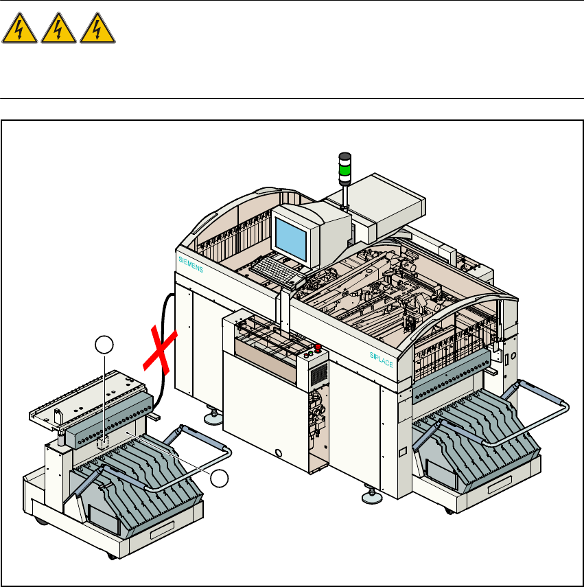
DANGER OF DEATH 7
The component table must be uncoupled for rewiring. Both the power cable and the communica-
tion cable must be disconnected. 7
Fig. 7 - 1 Component table, transformer T1
(1) Transformer T1
(2) Top part of frame
7
2
1
2