00191498-01.pdf - 第36页
Power supply Conversion Instructions S-20/S-23 HM/F4/F5 9 Inserting plug-in adapter X1 i nto the service socket 09/99 edition 36 Fig. 8 - 3 Wafflep ack changer transform er T1, connection: 3 x 230 V A C 9 Inserti ng plug…
Conversion Instructions S-20/S-23 HM/F4/F5 Power supply
09/99 edition
35
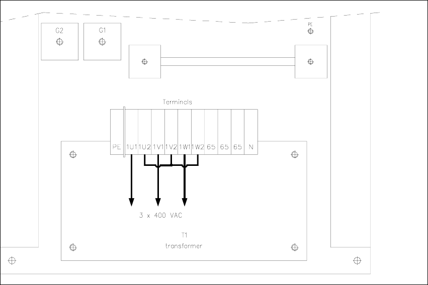
Å Remove the two jumpers between terminals 1U2 - 1V2 and 1V2 - 1W2 (see Fig. 8 - 2).
Fig. 8 - 2 Wafflepack changer transformer T1, connection: 3 x 400 VAC
8
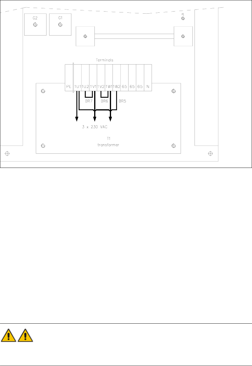
Å Place three jumpers between the following terminals:
1U1 → 1W2 BR5 (see Fig. 8 - 3)
1U2 → 1V1 BR7 (see Fig. 8 - 3)
1V2 → 1W1 BR6 (see Fig. 8 - 3)
Å Finally, replace the cover on the back of the wafflepack changer.
Power supply Conversion Instructions S-20/S-23 HM/F4/F5
9 Inserting plug-in adapter X1 into the service socket 09/99 edition
36
Fig. 8 - 3 Wafflepack changer transformer T1, connection: 3 x 230 VAC
9 Inserting plug-in adapter X1 into the service socket
Å For the USA version, plug the USA adapter X1 into the service socket.
10 Converting the placement system, component
tables and WPC from 3x230 VAC/115 VAC
to 3x400 VAC/230 VAC
The wiring for the 3x400 VAC/230 VAC versions is illustrated in the figures for the previous sec-
tions. 10
WARNING 10
After rewiring the placement system, REMEMBER to covert the component tables and wafflepack
changer as well, otherwise the transformers may be damaged. 10
Conversion Instructions S-20/S-23 HM/F4/F5 Power supply
09/99 edition
37
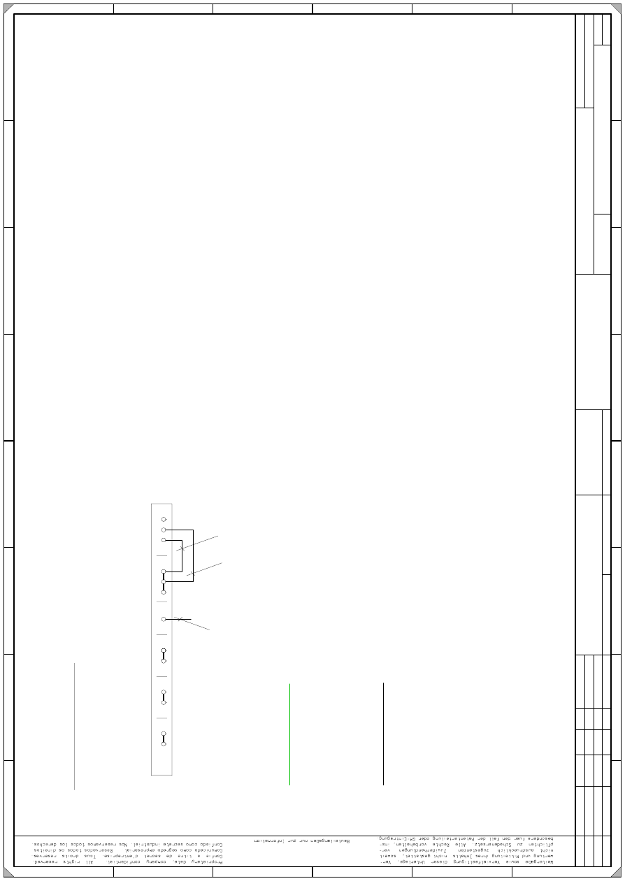
11 Appendix (Circuit diagrams)
=
G
e
pr.
N
o
rm
B
ea
rb
.
U
rspr.
E
rs. f.
E
rs. d
.
N
a
m
e
S
IE
M
E
N
S
A
G
+
P
E
L
2
L
2
3
1
7
A
F
C
D
2
L
1
E
D
L
1
5
4
6
N
L
3
L
3
5
P
E
3
7
8
C
B
A
N
N
5
F
6
8
1
4
B
W
a
W
a
T
ek
0
1.
0
1.
0
1.
1
4.1
0
.98
1
4.1
0
.98
14
.10
.1
9
98
B
er
ge
r
#
0
0
1
1
7
18
5
-0
10
1
01
L
D
3
1
0.0
3
.
99
E
X
2
06
2
P
E
P
L E
A
1 E
2
3
1
2
gn
ye
B
R
3
2,5
m
m
2
B
R
4
g
nye
P
o
w
er sup
p
ly un
it (con
trol
u
nit)
2
,5
m
m
2
15
0V
/ 6
0H
z
rd
2,5m
m
T
e
rm
in
a
l p
a
n
e
l ( righ
t-h
a
n
d
s
id
e
)
S
e
ctio
n
a
):
D
a
te
S
hee
t
D
a
te
M
od
ifi
catio
n
Issu
e
S
h.
fo
r S
IP
LA
C
E
80 S
20 / S
23
/ F
4 / F
5
S
IP
L
A
C
E
8
0
S
2
0
/ S
23
/ F
4
/ F
5
S
M
D
P
lacem
e
nt S
ystem
F
unctio
n statu
s
P
rodu
ct status
D
o
cu
m
en
t sta
tu
s
110/20
8V
C
onversio
n K
it
P
lease n
ote T
N
-C
syste
m
In a four-w
ire T
N
-C
syst
em
, the n
eutral and P
E
co
nductor functio
ns
m
ust be
co
m
bin
ed in a
single cond
u
ctor
the P
E
N
c
onducto
r
through
ou
t the entire system
(jum
pers B
R
3/B
R
4).
P
lease n
ote T
N
-S
system
J
um
pers B
R
3
/B
R
4 m
ust n
o
t be used
in a five-w
ire T
N
-S
system
.
(T
he n
eutral a
nd P
E
conductors are kep
t separate through
out the
system
).