5OM-1840-001w_F8S.pdf - 第61页
5OM-1840 Pneumatic and Mounting Diagrams 1-1-4 1604-001 Main Body (Mounting Diagram) 1 1-4 1-1 1-3 1-2 3-1 3-5 3-4 3-3 3-6 2-4 2-9 2-6 2-5 2-1 2-8 2-3 2-11 2-9 2-2 2-10 2-7 3-2 3-1 3 2 No. Name Q’ty No. Name Q’ty No. Nam…
5OM-1840
Pneumatic and Mounting Diagrams
1-1-3
1604-001
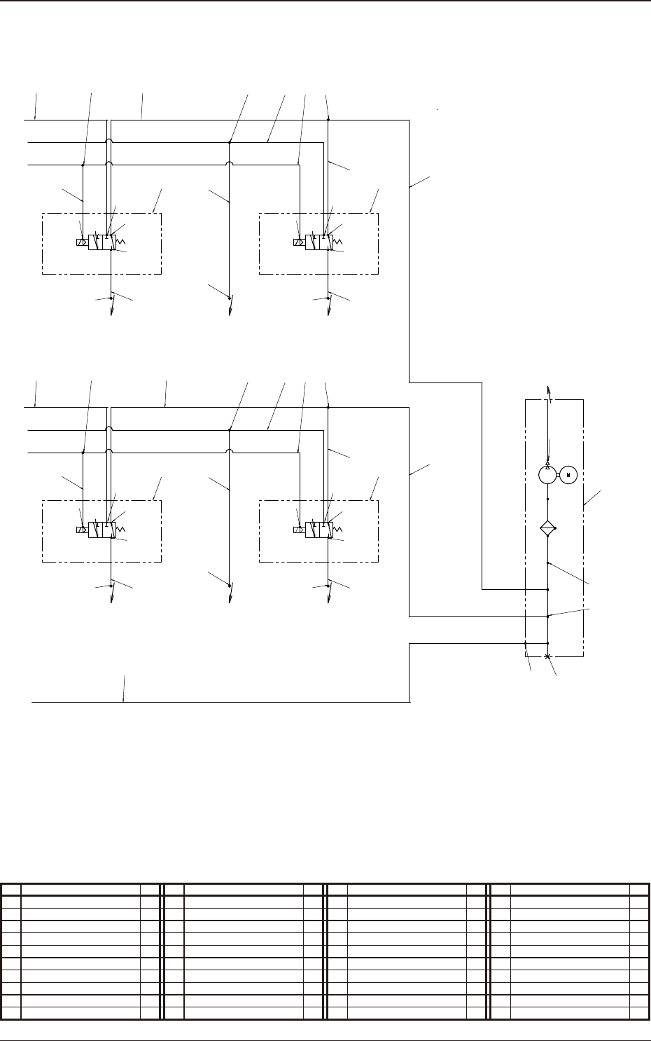
Main Body (Pneumatic Diagram)
A
P
R
Φ10(Blue)
300mm
Φ8 (Blue)
2000mm
Exhaust
Head(12)
Head(22)
Φ8 (Blue)
720mm
Φ6
770mm
Φ6
400mm
Φ8(Blue)
400mm
Φ6
70mm
Φ10 (Blue)
1200mm
Φ6
400mm
Ø8 (Blue)
400mm
Φ6
2000mm
Φ8(Blue)
2000mm
Φ6
150mm
Φ6
70mm
Φ6
70mm
Φ8(Blue)
70mm
Φ6
70mm
Φ6
150mm
Φ8
100mm
φ6 (Blue)
1100mm
Φ10(Blue)
2050mm
Φ8
500mm
A
P
R
A
Air/Vacuum Mode Change Valve
P
R
A
P
R
KQ2H06-02S
KQ2H08-02S
KQ2H08-01S
KQ2H06-M5
MBA1403
MPG14
KQ2R06-10
MHQ1410
KQ2L10-03S
11
11
11
11 15
11
11
11
24
24
11
14
15
15
28
15
16
15
15
16
15
24
KQ2U06-00
KQ2U06-00
24
KQ2U06-00
19
3
4
KQ2H08-00
22
21
KQ2U08-10
22
KQ2U06-00
24
4
4
4
22
KQ2H08-00
KQ2H06-00
KQ2H08-00
KQ2H06-00
22
21
KQ2H08-00
22
KQ2U08-10
27
KQ2H06-02S
KQ2H08-01S
KQ2H06-M5
KQ2H06-02S
KQ2H08-02S
KQ2H08-02S
KQ2H08-02S
KQ2H08-01S
KQ2H06-M5
KQ2H06-02S
KQ2H08-01S
KQ2H06-M5
Head(11)
Head(11)
Air/Vacuum Mode Change Valve
Air/Vacuum Mode Change Valve
Air/Vacuum Mode Change Valve
Head(21) Head(21)
No. Name Q’ty No. Name Q’ty No. Name Q’ty No. Name Q’ty
1 Air Supply Unit 1 6 Manifold Unit 1 23 Different Cheese 1
2 Air Supply Unit 1 7 Manifold Unit 1 24 Union Y 6
2-1 Vacuum Gauge 1 11 Tube
φ
6 1 25 Union Y 3
2-2 Combination Unit 1 12 Tube
φ
8 1 26 Different Union Y 5
2-3 Pressure Switch 1 13 Tube
φ
10 1 27 Different Union Y 2
2-4 Pressure Gauge 1 14 Tube
φ
6BU 1
2-6 Regulator 1 15 Tube
φ
8BU 1
2-7 Regulator 1 16 Tube
φ
10BU 1
3 Vacuum Pump Unit 1 21 Straight 6
4 Solenoid Valve Unit 4 22 Straight 6
5OM-1840
Pneumatic and Mounting Diagrams
1-1-4
1604-001
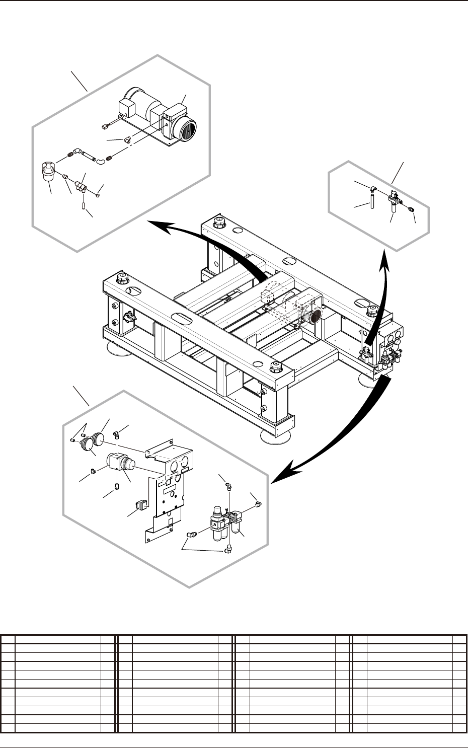
Main Body (Mounting Diagram)
1
1-4
1-1
1-3
1-2
3-1
3-5
3-4
3-3
3-6
2-4
2-9
2-6
2-5
2-1
2-8
2-3
2-11
2-9
2-2
2-10
2-7
3-2
3-1
3
2
No. Name Q’ty No. Name Q’ty No. Name Q’ty No. Name Q’ty
1 Air Supply Unit 1 2-5 Regulator 1 3-3 Universal Quick 3
1-1 Combination Unit 1 2-6 Elbow Union 1 3-4 Plug 1
1-2 Female/Male Elbow 1 2-7 Half Union 2 3-5 Elbow Union 1
1-3 Single-Ended Hose Nipple 1 2-8 Half Union 1 3-6 Reducer 1
1-4 Half Union 1 2-9 Elbow Union 1
2 Air Supply Unit 1
2-10
Elbow Union 1
2-1 Vacuum Gauge 1
2-11
Elbow Union 2
2-2 Combination Unit 1 3 Vacuum Pump Unit 1
2-3 Pressure Switch 1 3-1 Vacuum Pump 1
2-4 Pressure Gauge 1 3-2 Bush 1
5OM-1840
Pneumatic and Mounting Diagrams
1-1-5
1604-001
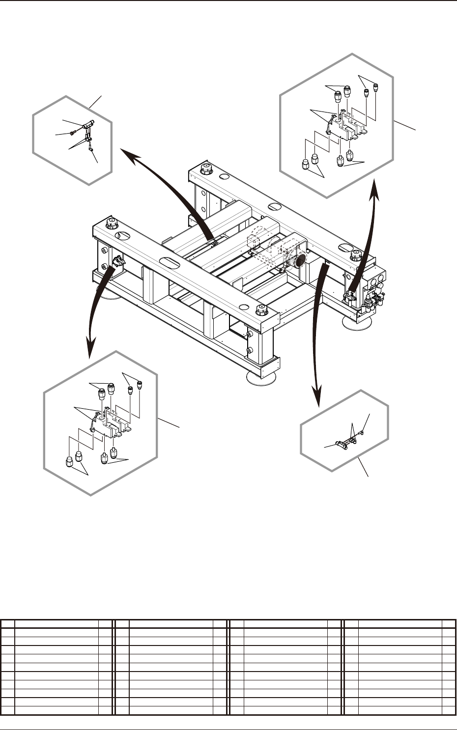
Main Body (Mounting Diagram)
6
7
7-1
6-1
7-2
6-2
7-3
6-3
7-4
4
4-1
4-2
4-3
4-5
4-4
4
4-1
4-2
4-3
4-5
4-4
No. Name Q’ty No. Name Q’ty No. Name Q’ty No. Name Q’ty
4 Solenoid Valve Unit 1 7 Manifold Unit 1
4-1 Solenoid Valve 2 7-1 Manifold 1
4-2 Half Union 2 7-2 Straight Elbow 2
4-3 Half Union 2 7-3 Reducer Elbow 1
4-4 Half Union 2 7-4 Plug 1
4-5 Half Union 2
6 Manifold Unit 1
6-1 Manifold 1
6-2 Straight Elbow 2
6-3 Reducer Elbow 1