00198356-01_AI_Input-Extension_SX12_DE_EN_web - 第57页
Assembly Instructions / Montageanleitung SIPLACE SX1/SX2 V2 Option Input Conveyor Extension 05/2017 3 Installation 3.2 Dismantling any available belt guides 57 3.2 Dismantling any available belt guides This section descr…
3 Installation
3.1 Preparing the machine
Assembly Instructions / Montageanleitung SIPLACE SX1/SX2 V2
Option Input Conveyor Extension 05/2017
56
3.1 Preparing the machine
► Use the software or manually move the conveyor rail into a position which allows you best ac-
cess.
CAUTION
Moving the conveyor rails
The conveyor rails are highly sensitive and should therefore not be moved unless you have
released the brakes.
If you do move them without releasing the brakes, this could cause irreparable dam-
age to the conveyor rails.
► We recommend that you use the software to help you move the conveyor rails.
► If this is not possible, the conveyor rails of the dual conveyors can also be moved by
manually docking in the adjustment units. Make sure that the cylinders engage in all
clamping units of a particular conveyor rail. The conveyor rails can then be moved by
carefully pulling the toothed belt of the width adjustment unit.
► If this is not possible either, the brakes of the dual conveyors can manually be re-
leased using a pin. Take special care not to distort the conveyor rails.
► Switch off the machine, disconnect it from the power supply and secure it to prevent
unauthorized reactivation. Observe the instructions in section 1.2 "Preparatory Work..." [}46].
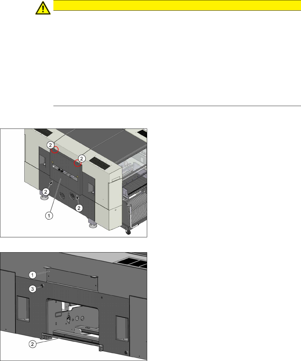
Fig.6: Cover on the input side
► Remove the four screws (2) fastening the cover
(1) (tiny backpack) and remove the cover.
Fig.7: Brackets
► Remove the top bracket (1).
► Remove the bottom bracket (2) (guide rail for
PCB barcode).
► Remove the stop roll (3).
Assembly Instructions / Montageanleitung SIPLACE SX1/SX2 V2
Option Input Conveyor Extension 05/2017
3 Installation
3.2 Dismantling any available belt guides
57
3.2 Dismantling any available belt guides
This section describes how to dismantle the belt guides which are installed in the standard con-
veyor.
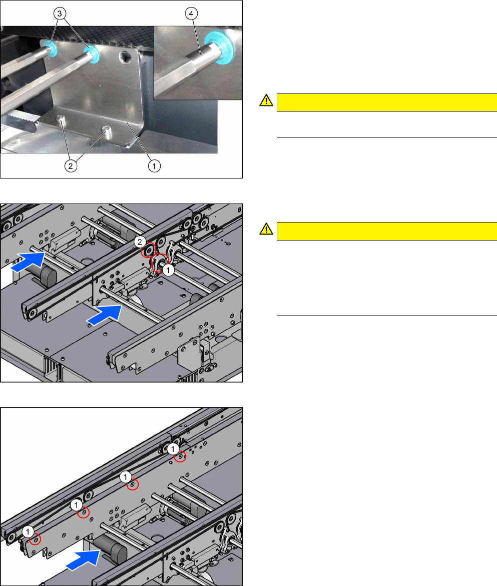
Fig.8: Hexagonal shaft
In order to unthread the conveyor belt, the hexagonal
shaft of the corresponding drive must be dismounted
(see the next steps).
To do so, proceed as follows:
► Remove the screws (2) that are fastening the
bracket (1). See also: 4.1.1 "Replacing the
Hexagonal Shaft [03094006-xx]" [}63].
CAUTION!
Make sure you do not lose the green plastic
bearings(3).
.
If required, use two fork wrenches to dismantle the
ends (4) of the hexagonal shafts. This makes more
room for moving the hexagonal shafts.
Fig.9: Movable idler pulley and drive
► Loosen the movable idler pulley (2).
CAUTION!
Only loosen!
Make sure you do not unscrew the movable idler
pulley completely. Otherwise, the counterpart in-
side the conveyor rail may fall out.
The lack of room makes subsequent insertion
and fixture of the counterpart highly complicated.
.
For an overview of the individual movable idler pulleys,
see section 4.1.6 "Belt Tension" [}69].
► Remove the screws fastening the drive (1) of the
hexagonal shaft. See also: .4.1.2 "Replacing the
Tape Drive [03092315-xx]" [}64]
Fig.10: Belt guide
► Dismount the belt guide. To do so, remove the
four countersunk screws (1) at the upper side of
the conveyor rails.
See also: 4.1.4 "Replacing the clamping rail and
belt guide" [}66].
► Unthread the conveyor belt.
See also: 4.1.5 "Replacing the Toothed Belt
(Conveyor Belt)" [}68]
► Repeat these steps for all conveyor rails.
3 Installation
3.3 Preparing the extensions
Assembly Instructions / Montageanleitung SIPLACE SX1/SX2 V2
Option Input Conveyor Extension 05/2017
58
3.3 Preparing the extensions
This section describes how to prepare the input conveyor extensions for the installation:
●
Input conveyor extension A/C complete [03127428-xx]
●
Input conveyor extension B/D complete [03127427-xx]
NOTICE
Example
The "Input conveyor extension A/C complete" [03127428-xx] is taken as an example to
show the preparation of the extensions.
The preparation of the "Input conveyor extension B/D complete" [03127427-xx] follows the
same procedure.
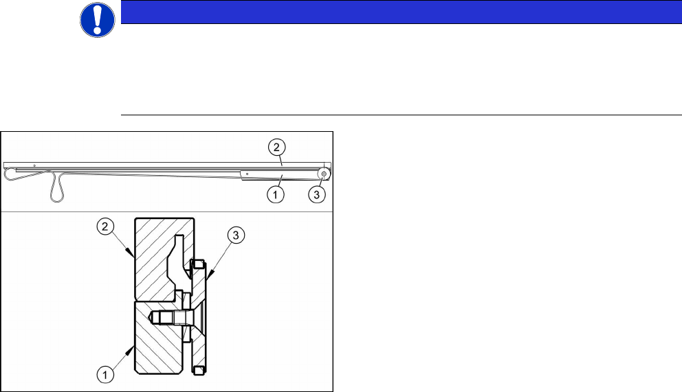
Mounting the stiffening bar (example shows the con-
veyor rail A/C)
1. Stiffening bar (idler pulley mount) [03127457‑xx]
2. Belt guide extension [03127426‑xx]
3. Idler pulley [03099834‑xx]
► Use three screws of type ISO4762-M3x12-A2-70
[03042544 xx] to fasten the stiffening bar(1) to
the belt guide extension(2).
► Dismount the idler pulley (3) from the dismantled
belt guide and mount it on the belt guide exten-
sion.
► Repeat these steps for all conveyor rails.