00198356-01_AI_Input-Extension_SX12_DE_EN_web - 第62页
3 Installation 3.6 Setting the belt tension Assembly Instructions / Montageanleitung SIPLACE SX1/SX2 V2 Option Input Conveyor Extension 05/2017 62 Fig.19: Attaching the stickers ► If not present, attach the respective s…
Assembly Instructions / Montageanleitung SIPLACE SX1/SX2 V2
Option Input Conveyor Extension 05/2017
3 Installation
3.5 Mounting the hand guard belt extension
61
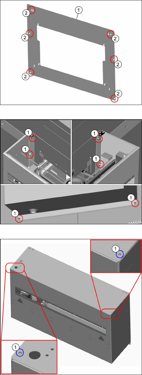
Fig.16: Adapter plate
► Hook the hand guard belt extension
[03100054‑xx] onto the six threaded pins (2) of
the adapter plate (1).
Fig.17: Mounting the hand guard belt extension
► Use six self-locking M6-8 [03010700‑xx] nuts (1)
to fasten the hand guard belt extension.
Fig.18: Fastening the top cover
► Fix the top cover with two fastening screws(1).
This is necessary to prevent someone from reaching
into the running machine.
3 Installation
3.6 Setting the belt tension
Assembly Instructions / Montageanleitung SIPLACE SX1/SX2 V2
Option Input Conveyor Extension 05/2017
62
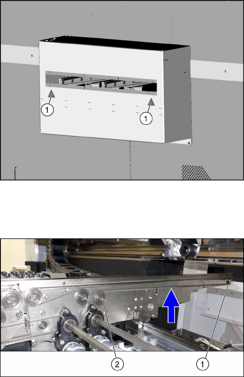
Fig.19: Attaching the stickers
► If not present, attach the respective stickers(1) to
the hand guard belt extension.
3.6 Setting the belt tension
Measuring the belt tension
► Set the tension of the new conveyor belt for all
conveyor rails.
To do so, measure the distance between the first
idler pulley (1) and the movable idler pulley (2)
from center to center (585 mm distance).
The belt tension here is about 34Hz+/‑10%.
See also: 4.1.6.2 "Calculating the Belt Ten-
sion" [}71].
Assembly Instructions / Montageanleitung SIPLACE SX1/SX2 V2
Option Input Conveyor Extension 05/2017
4 Appendix
4.1 Excerpts from the Service Manual
63
4 Appendix
4.1 Excerpts from the Service Manual
The following chapters are excerpts from the service manual for your machine. If required, further
information is provided there.
●
Service Manual SIPLACE SX1/SX2 V2 [DE:00196999‑xx] [EN:00197000‑xx]
4.1.1 Replacing the Hexagonal Shaft [03094006-xx]
Parts, equipment and tools
●
Hexagonal shaft SX1a [03094006-xx]
●
Bearing for hexagonal shaft SXa (plastic bearing) – pack of 10 [03092024-xx]
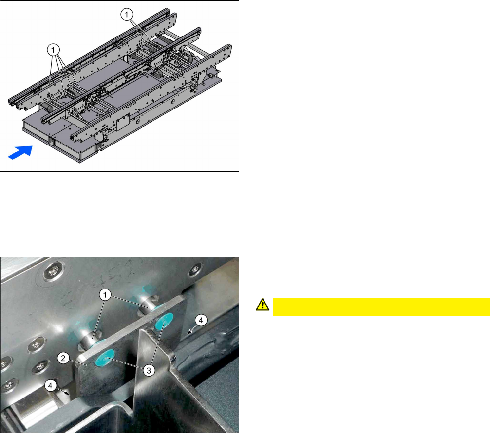
Overview
1. Hexagonal shafts
Removal
► Use the software to move the conveyor rails into a position which allows you best access. Al-
ternatively, you can also loosen the conveyor rail clamps on the dual conveyor.
► Switch off the machine, disconnect it from the power supply and secure it to prevent unauthor-
ized reactivation. Observe the instructions in section 1.2 "Preparatory Work..." [}46].
► Loosen the screws (4) fastening the hexagonal
shaft mount (2) and remove the plastic bearings
(3) on both sides of the conveyor.
CAUTION!
The hexagonal shafts (1) are fixed on both sides
of the conveyor with brackets. When you dis-
mantle the hexagonal shaft, you only need to
take off one of these brackets.
Make sure that you do not lose the plastic bear-
ings. When you dismantle a bracket, always re-
move all the plastic bearings on this bracket and
the opposite bracket. These would otherwise ob-
struct the movement of the hexagonal shafts and
could easily fall out.
.