00198356-01_AI_Input-Extension_SX12_DE_EN_web - 第67页
Assembly Instructions / Montageanleitung SIPLACE SX1/SX2 V2 Option Input Conveyor Extension 05/2017 4 Appendix 4.1 Excerpts from the Service Manual 67 Fig.20: Grub screw (here: output area) ► Input and output areas only…
4 Appendix
4.1 Excerpts from the Service Manual
Assembly Instructions / Montageanleitung SIPLACE SX1/SX2 V2
Option Input Conveyor Extension 05/2017
66
Installation
► Follow the removal instructions in reverse order for installation. Also observe the following in-
structions:
CAUTION
Installation instructions
► Make sure that the toothed belt is not folded or damaged otherwise.
► Make sure that the toothed belt is accurately positioned in the guidance on the motor
shaft.
► While tightening the movable idler pulley, set the tension of the toothed belt correctly
(see 4.1.6.1 "Setting the Tension of the Conveyor Toothed Belt" [}69]).
► Check if the belt drive and the drive unit are correctly aligned to each other.
To do so, push the conveyor rails together until a gap is left that is wide enough so
you can still just reach the fastening screws.
Check the conveyor drive for ease of movement by turning the hexagonal shaft. You
may need to loosen the conveyor drive again and then reset it.
► Use cable ties to fix the cables to the motor.
Make sure that the cables are not dragged along during operation.
Make sure that the cables are not being damaged on edges or rubbed against any-
thing when you adjust the conveyor rails.
► Make sure you tighten the fastening screws with a torque of 1.7Nm.
► Make sure the washers are in the correct position.
4.1.4 Replacing the clamping rail and belt guide
Parts, equipment and tools
Select the required belt guide or clamping rail.
Input area Placement area Output area
Conveyor rails
A and C
Belt guide A/C IC SX1a
[03094979‑xx]
Default:
Clamping rail PA SX1
complete
[03093199‑xx]
For Thick Board option:
Clamping rail for thick
board SX1a complete
[03099567‑xx]
Belt guide A/C AB
SX1a [03094510‑xx]
Conveyor rails
B and D
Belt guide B/D EB
SX1a [03095033‑xx]
Belt guide B/D AB
SX1a [03094630‑xx]
Removal
CAUTION
Carefully move the conveyor rails!
Without the clamping rail and the belt guides, the conveyor rails lack significant support ele-
ments.
► Move the opened conveyor rails only very carefully.
Make sure you always push both the left and the right conveyor rail equally.
Also make sure that you do not distort the conveyor rails.
► Use the software to move the conveyor rails into a position which allows you best access. Al-
ternatively, you can also loosen the conveyor rail clamps on the dual conveyor.
► Switch off the machine, disconnect it from the power supply and secure it to prevent
unauthorized reactivation. Observe the instructions in section 1.2 "Preparatory Work..." [}46].
► Only in the input and output areas: Loosen the movable idler pulley of the conveyor belt (see
also 4.1.6.1 "Setting the Tension of the Conveyor Toothed Belt" [}69]).
Assembly Instructions / Montageanleitung SIPLACE SX1/SX2 V2
Option Input Conveyor Extension 05/2017
4 Appendix
4.1 Excerpts from the Service Manual
67
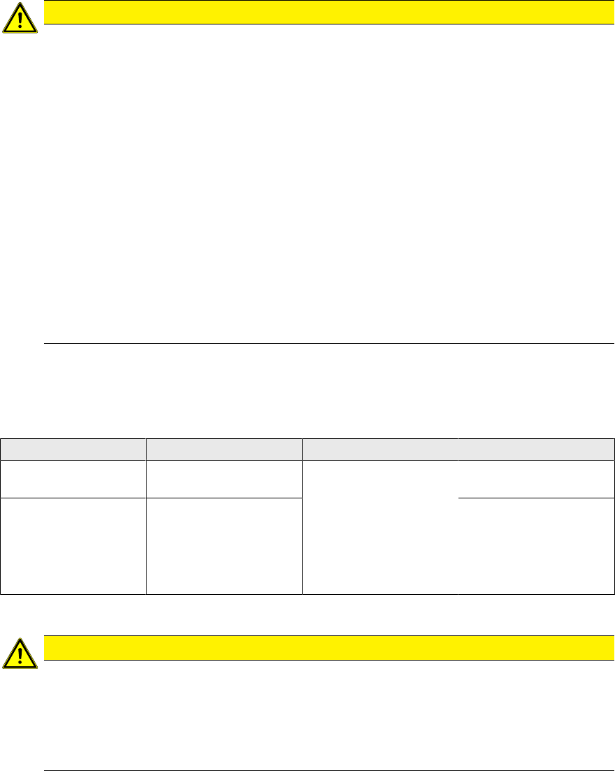
Fig.20: Grub screw (here: output area)
► Input and output areas only:
If a receiver is fixed to the belt guide, loosen the grub screw (1) fixing the receiver.
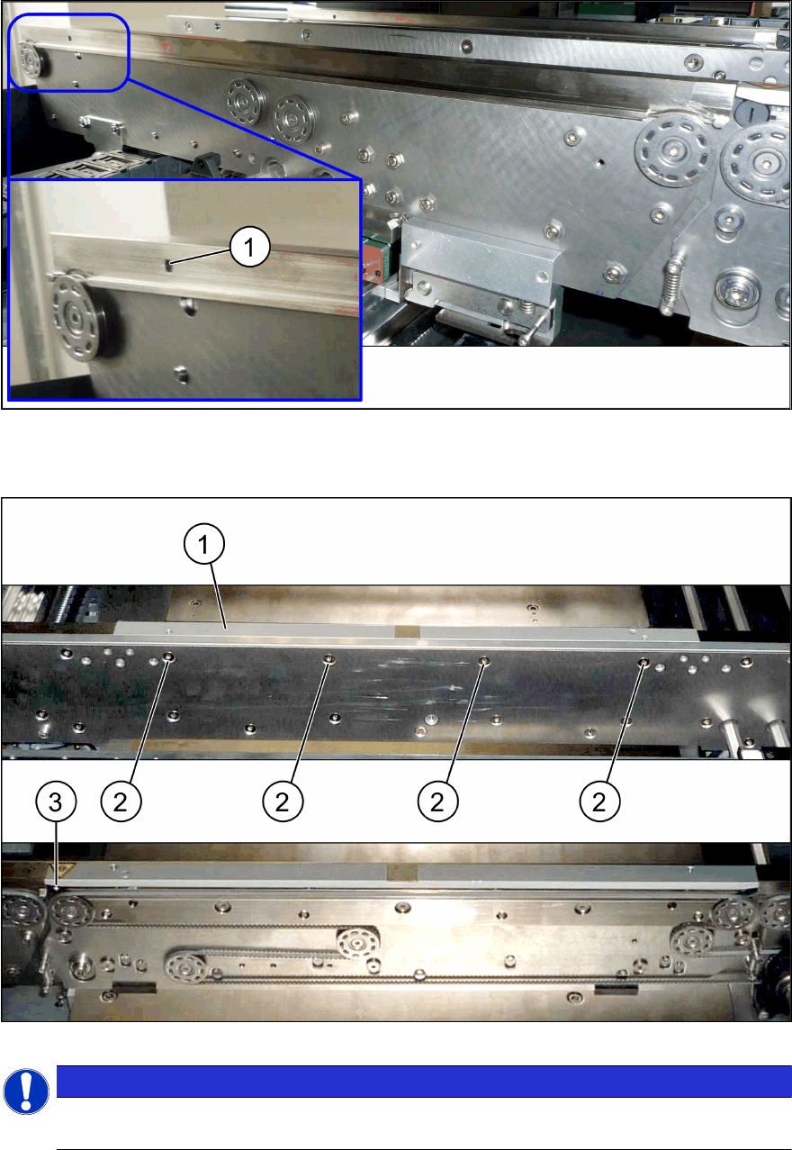
► Remove the four screws (2) fastening the clamping rail / belt guide(1).
NOTICE
Special screws
These are special screws with a length of 14.7 mm.
► Carefully pull the clamping rail / belt guide up and off the conveyor rail.
► You may need to dismantle the transmitter / receiver fixed to the clamping rail.
4 Appendix
4.1 Excerpts from the Service Manual
Assembly Instructions / Montageanleitung SIPLACE SX1/SX2 V2
Option Input Conveyor Extension 05/2017
68
Installation
► Follow the removal instructions in reverse order for installation. Also observe the following in-
structions:
CAUTION
Installation Instructions
► Tighten the screws fastening the clamping rail / belt guide with a torque of 6Nm. Oth-
erwise, the thread could be damaged or the conveyor rail could be distorted.
► Check the setting for the transmitter / receiver and correct it if necessary (see Setting
and Correcting the Laser Light Barrier).
► Once you have loosened the conveyor belt, set the tension again (see 4.1.6.1 "Setting
the Tension of the Conveyor Toothed Belt" [}69]).
4.1.5 Replacing the Toothed Belt (Conveyor Belt)
Parts, equipment and tools
●
Toothed belt
Select the relevant toothed belt:
Input area Placement area Output area
Toothed belt Synchronous belt
L=1239mm
[03093312‑xx]
Synchronous belt
L=1500mm
[03093146‑xx]
Synchronous belt
L=1158mm
[03093314‑xx]
●
Bearing for hexagonal shaft SXa (plastic bearing) – pack of 10 [03092024-xx]
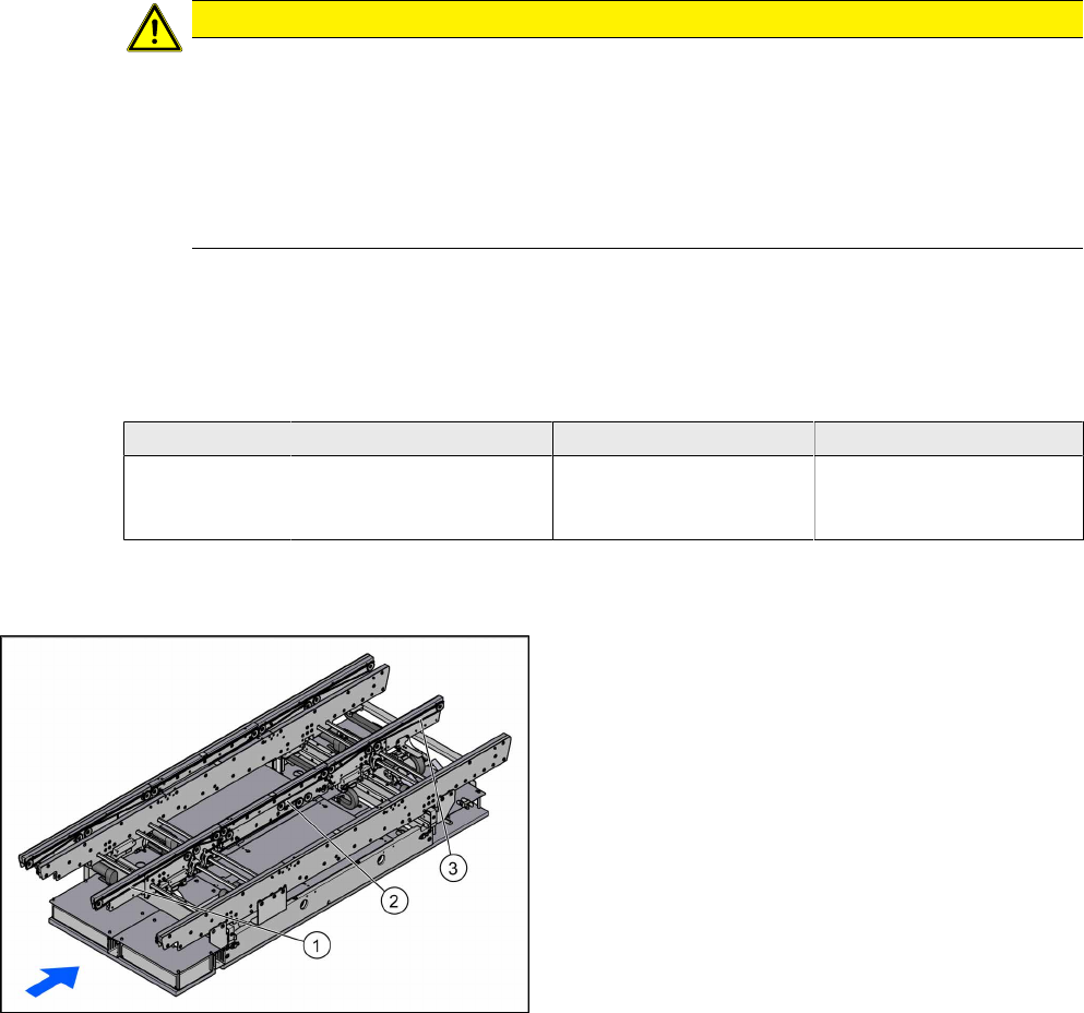
Overview
1. Toothed belt input area
2. Toothed belt placement area
3. Toothed belt output area
Removal
► Use the software to move the conveyor rails into a position which allows you best access. Al-
ternatively, you can also loosen the conveyor rail clamps on the dual conveyor.
► Switch off the machine, disconnect it from the power supply and secure it to prevent unauthor-
ized reactivation. Observe the instructions in section 1.2 "Preparatory Work..." [}46].
► Loosen the hexagonal shaft on the belt drive or conveyor drive (motor), so that you can move
the shaft freely. To do this, dismantle the hexagonal shaft fixture on one side and the corres-
ponding plastic bearing on both sides (see also 4.1.1 "Replacing the Hexagonal Shaft
[03094006-xx]" [}63]).
► Loosen the movable idler pulley (see also 4.1.6.1 "Setting the Tension of the Conveyor
Toothed Belt" [}69]).