HS50 circuit diagram - 第103页
2 Circuit Diagr ams 103 I 0033615 4-020 201 TD3 HS -50 mai n distr ibutor 1 A3 1 02. 14.01.1998 Hoffmann 11.09.98 26.01.99 FS ES US UA S F SMD Placement System SIPL ACE HS50 HS50 mai n distribut or Assembly inscrip tion …
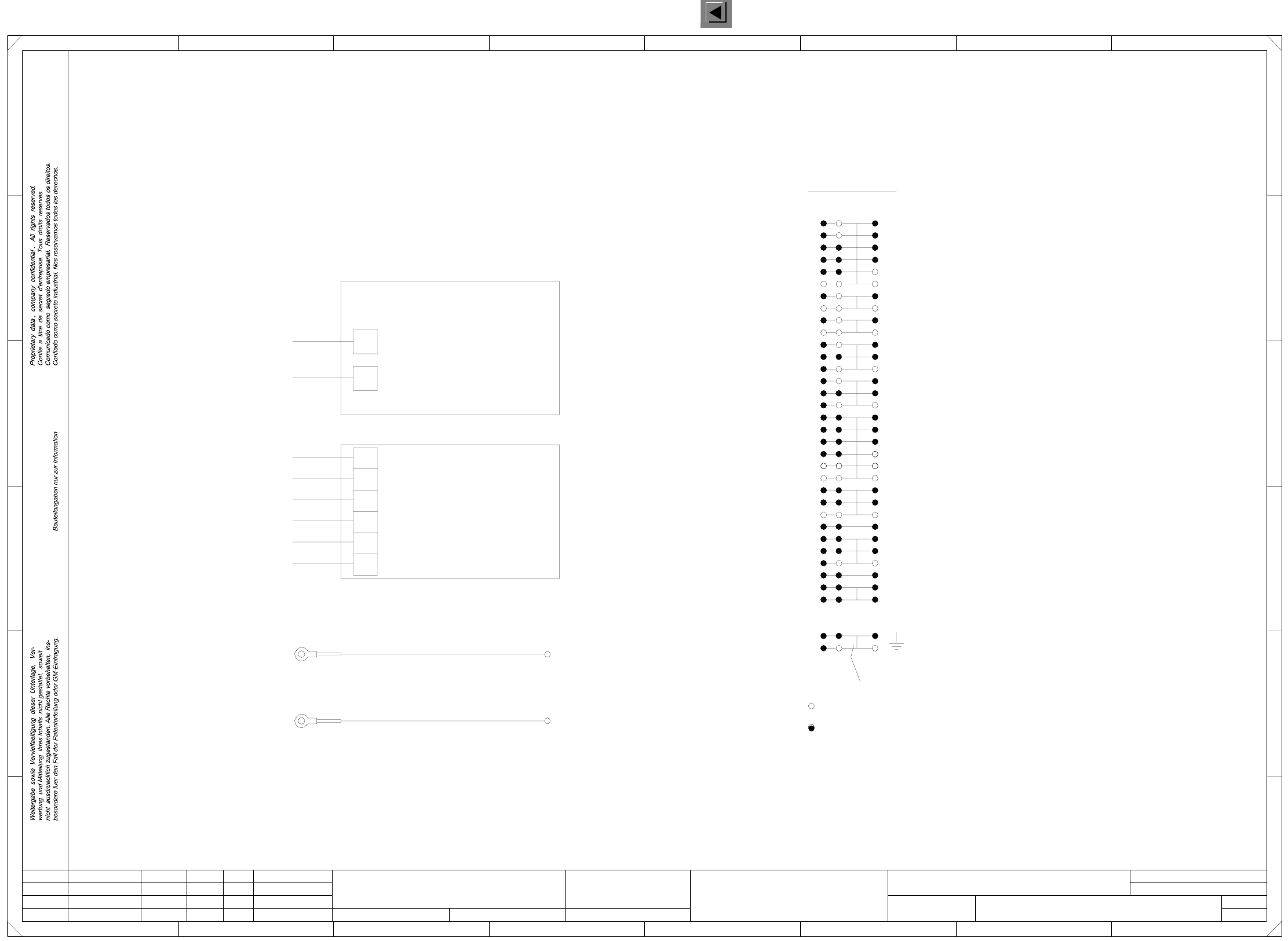
2 Circuit Diagrams 102
I
00336154-020101LD3 HS-50 main distributor (Sh. 5 of 5)
step motor
for
Stand.Status DateModified Name
Orig. Repl. f. Replaced by
Author
Check.
Date
Sheet
Sh.
13
14
15
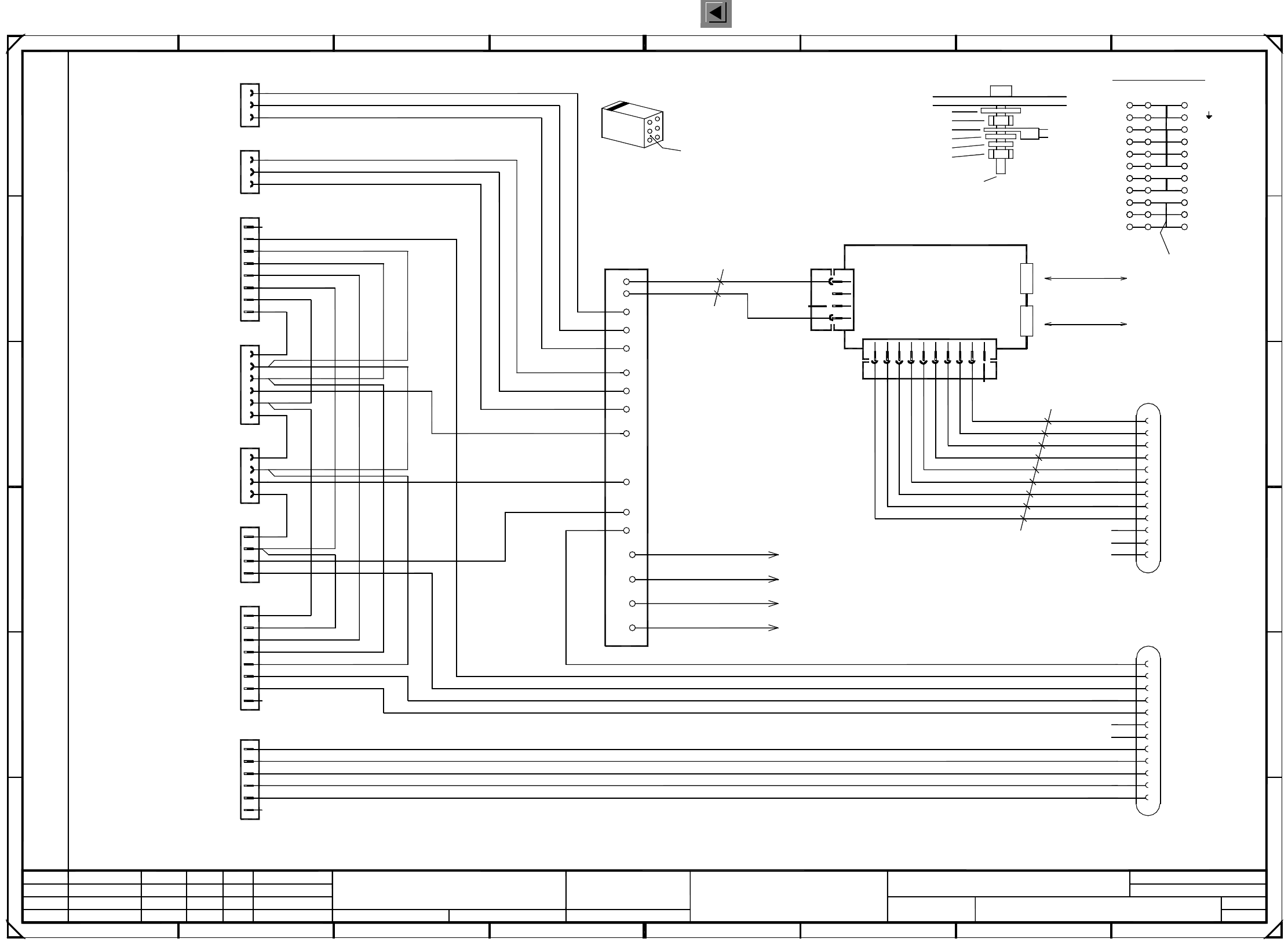
GND
GND
+5V
+24V
21a
21c
Bus bar
Conversion board
ab c
PE
PE
Jumper
Ground
X101/PE
X101/PE
To housing
main distributor
To main grounding point (MGP)
2,5mm²
gn/ye
2,5mm²
13
14
15
17
16
18
19
20
32
21b
5c
20c
+24V
+24V
+24V
Ill.VC
Ill.PCB
Ill.1
Ill.2
Ill.3
GND
camera illumination
for
X101 terminal overview
B
F
E
D
C
23
5
1P34V
2P34V
P48V
Terminal not used
Terminal used
Conversion board
37a
Bus bar
+34V
87
1 45
F
678
1234
E
C
D
gn/ye
00336179
00336188
with M5 annular cable lug
with M5 annular cable lug
22 22
01.
01.
02.
Tek
Tek
Tek
5
5
/ 300mm
B
A
6
A
PL EA1 E2
11.09.98
00336154-020101LD3
HS50 main distributor
Hoffmann
06.03.1998
11.09.98
11.09.98
=
SIEMENS AG
+
17
16
18
19
20
32
31
33
34
35
39
2
1
3
4
5
6
7
8
9
11
10
12
2
1
3
4
ab c
5
6
31
33
34
35
3636
39
21 21
3737
3838
4040
+5V
-12V
+12V
-15V
+15V
+24V
P8V
P34V
7
8
9
11
10
12
Function status
Product status
Doc. status
SMD Placement System SIPLACE HS50
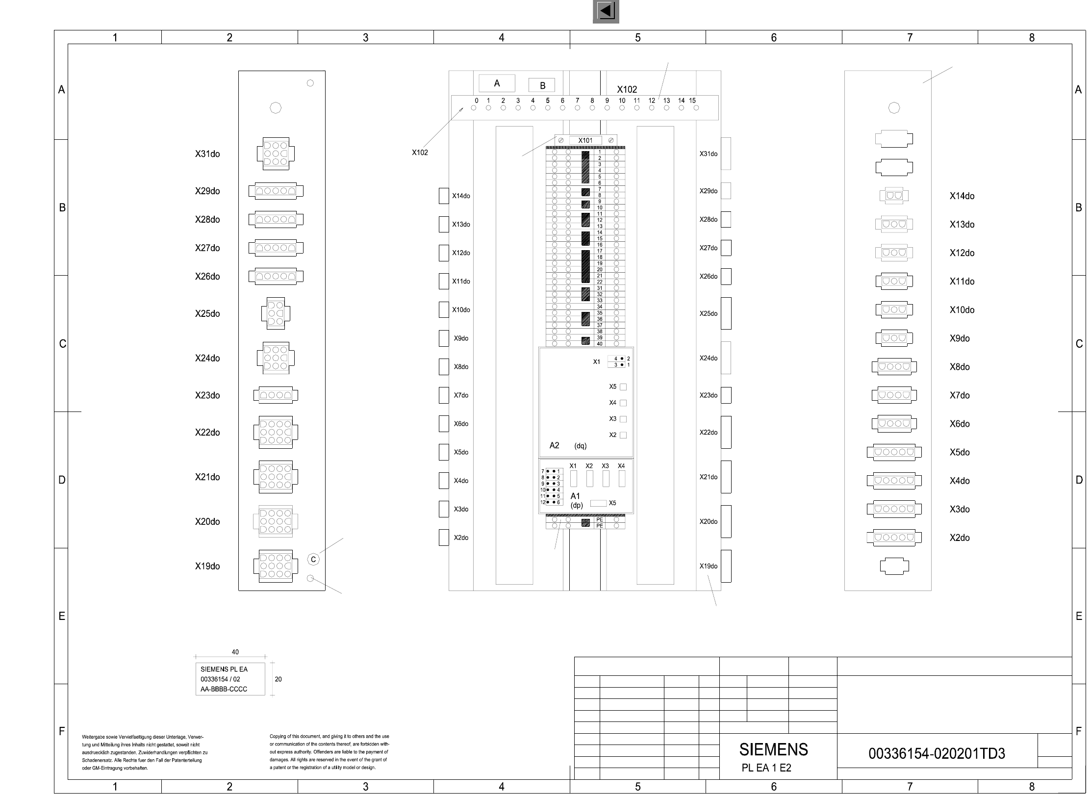
2 Circuit Diagrams 103
I
00336154-020201TD3 HS-50 main distributor
1
A3
1
02.
14.01.1998 Hoffmann
11.09.98
26.01.99
FS ES US UA S F
SMD Placement System SIPLACE HS50
HS50 main distributor
Assembly inscription according to VA-F-510-001
Fonz size 2.5 mm, material Scotchal 3698-E (color A1 RAL 9006)
AA = numerals
BBBB = date (year/month/day) acc. to SN 01007
CCCC = manufacturer/location of plant acc. to SN 37040
Identification: testing engineer, month, year
The following labels have to be applied:
C: PE label (gn/ye)
A: identification label
B: inspection label
* Please note:
Doc. status
Product status
Function status
and a grey 3-pole terminal block with a yellow/green jumper.
’PE terminal block’ made of a yellow/green 3-pole terminal block
Fix cable ducts by means of double-sided adhesive tape.
Ground hole
Plug inscription on edge,
font size 4 mm
on the inside
PE label (gn/ye),
Cable duct 65x30mm l=370mm (part 006)
gn/ye
(inscription)
Part 005
Cable duct 65x30mm l=370mm (part 006)
Part 002
Part 001
Status Modified Date Name
Author
Check.
Stand.
Date
Name
(Drawing number)
Main no.
Sheet
Sh.
26.01.99
Tek
Tek
Tek
02.
01.
26.01.99
2 Circuit Diagrams 104
I
00336181-030201LD3 Distributor, sector 2
3 6
A
B3
B4
B5
B6
B8
CANL
ab
87
A1 CAN-bus coupler
00332557 (bg)
B10
B11
B12
B2
E
B
56
3
2
key
+5V
X3bg and X4bg
A2
A1
A9
A6
A4
A8
A3
A5
A12
A11
A10
A7
X1bf
87
500kbps
CAN bus
CANH
Ground connection :
0.56mm² / bk
0.56mm² / bk
M5 hexagon nut, DIN 439
Distributor sheet
Locking clip plug:
c
PE
GND
B7
F
5
B
D
C
GND
+5V
+24V
Jumper
PE
PE
1P34V
GND
A module
P8V
N8V/34V
X2bg
X3bg
CAN bus
500kbps
CAN_INT
CAN_RESET
Function stat.
01.
03.
Tek
Tek
Tek
1
M5 hexagon nut, DIN 439
Contact washer
00336787gnye
To machine frame
00336788gnye
To distributor sheet
00336789gnye
To cover
Annular cable lug
8 / 9
2
2
5
4
7
02.
25.03.99
1
00336181-030201LD3
Distributor, sector 2
Hoffmann
11.12.1997
13.01.00
13.01.00
Document stat.
Product stat.
6
3
3
1
4
2
6
3
4
5
3
8 / 9
2
1
3
2
1
4
5
3
1
7a
PE
PE
PE
3c
7c
1
7
6
2
4
2
1
1
5
4
3
2
1
PE
that the numerical sequence of a locking clip plug
Please note that ...
must be as viewed from the rear side of the casing.
Cable
3
3
6
GROUND
6a
1
2
2
3
PL EA1 E2
8
8
9
910
1
2
3
4
7b
5
56
6
7
7
1a
2c
4c
6c
2a
4a
14
4
1
4
4b
Spare
S_CompEnd
S_hood
S_StartButton
S_Emerg.StopButton
S_CompFlap
S_StopButton
L_End
L_Begin
S_hood
S_StartButton
S_StopButton
L_End
L_Begin
S_hood
L_End
L_Begin
S_CompFlap
L_End
S_StopButton
S_CompFlap
S_Emerg.StopButton
S_StartButton
S_hood
L_End
S_CompEnd
Spare
PCC21
PCC22
Spare
Address bit 0
GND_Address
Address bit 1
Spare
Spare
Spare
S_Begin
L_Begin
L_End
S_End
Spare
Spare
PCC21
PCC22
ModifiedStatus Stand.Date Name Orig. Replaced byRepl. f.
Author
Check.
Date
Sheet
Sh.
Bauteilangaben nur zur Information
Weitergabe sowie Vervielfaeltigung dieser Unterlage, Ver-
wertung und Mitteilung ihres Inhalts nicht gestattet, soweit
nicht ausdruecklich zugestanden. Alle Rechte vorbehalten, ins-
besondere fuer den Fall der Patenterteilung oder GM-Eintragung.
Comunicado como segredo empresarial. Reservados todos os direitos.
Confie a titre de secret d’entreprise. Tous droits reserves.
Proprietary data , company confidential . All rights reserved.
Confiado como secrete industrial. Nos reservamos todos los derechos.
1P34V
P8V
N8V/34V
GND
+5V
Voltages ring circuit
Sec2<>Sec3
Infeed
Socket 2, peripheral modules
StartStopOutputLeft
HoodPCBOutput
Safety ring circuit
Sec1<>Sec2
Safety ring circuit
Sec2<>Sec3
SMD Placement System SIPLACE HS50
00336790gnye
8
To Harting plug housing (from X1)
+24V
+24V
+24V
X25bf
CompFlap2
X7bf
2
B9
M5 washer, DIN 125
M5 split washer, DIN 7980
M5x16 fillister head screw, DIN 912
+24V
GND
+5V
+24V
X5bf
X2bf
X8bf
X4bf
X6bf
X3bf
Hood2
All control lines: 1.00mm² / black
Cable ties are used to form the cable harness !
Voltages ring circuit
Sec1<>Sec2
432
1 4
10
key
X3bg
X200 terminals overview
B1
X1bf
B module
C
1
X4bg
X4bg
F
E
D
1
2
3
4
5
6
7
+5V
GND
X1bg
A
=
SIEMENS AG
+
3
5
2
4
6
1