HS50 circuit diagram - 第113页
3 OPTIONS Circuit Diagrams 113 I 001 19025-0201 01LD3 Dual conveyo r , stationary sid e on th e right, wiring fo r contr ol 1, T SP200 (Sh. 6 o f 7) Conve yor 1 pl ug X31am Motor line , P CB c onveyor HS50 C onveyor 1 00…
3 OPTIONS Circuit Diagrams 112
I
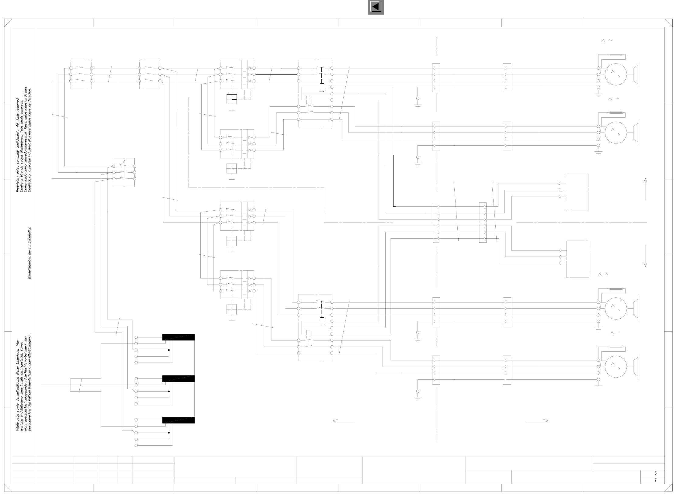
00119025-020101LD3 Dual conveyor, stationary side on the right,
power supply for lifting table motors 1-4, TSP200 (Sh. 5 of 7)
2
2.5mm²
X6ao
1.5mm²
MS4
0V
A
wh
bn
gn
wh
bn
Conveyor, track 2
M7_1
220V3
Lifting table motor 1
bk(1)
4
6
6
bk(3)
ye/gn
Motor: lifting table 3
Motor: lifting table 4
6
1
3
5
3
5
Null
1
4
8
6
3
4
2
3
4
2
3
X70
X6ao
with brake
00335215 Sh.2
X3ap
Conveyor control TSP200
dual conveyor
bk(2)
bk(3)
1
1.5mm²
15
14
4
2
4
6
1
00335214 Sh.2
St_Hub1
9
7
13
5
X11_4
4
2
5
3
1
11
9
Option
rd
56
SL
M
1
3
5
2.5mm²
U
V
W
(conveyor 2)
SL
K2
K3
K4
K6
K7
ye/gn
bk(2)
M8_2
220V3
Lifting table motor 3
bk(1)
bk(2)
bk(3)
with brake
M7_2
T1
F3
4A
2
2
4
S50 power supply unit PCB conveyor, lift. table motors
(conveyor 1)
(conveyor 2)
Single conveyor
M
3
A
rd
2.5mm²
ELR1
12
10
gn
2
dual conveyor
with brake
00335217 Sh.2
MS6
2
4
6
4
2
2
3
4
1
2
78
3
5
2.5mm²
1
3
13
Control signals
lifting table motors
00333592
400V
230V
0.75mm²
00337796
lifting table motor
bk(3)
ye/gn
00336121
placement section 4
Cable: lifting table motor
00335216 Sh.1
(conveyor 2)
230V
4mm²
X7_1
X7_3
X7_4
X7_2
X72
W
EEP
bk(1)
K8
MS3
2
440V
1
2
X11_1
X11_2
bk(3)
ye/gn
220V3
Lifting table motor 4
00335215 Sh.1
(conveyor 1)
V
W
EEP
230V
440V
400V
230V
bk(3)
ye/gn
00335216 Sh.2
Transformer
MS5
2
4
X6ap
X6ap
ye/gn
3
5
SZ2 SZ3
infeed
4mm²
1
11
X8_2
X73
1
14
15
X11_5
6X11_6
X5_1
X5_3
X5_4
X5_2
W
EEP
St_Hub2
St_Hub3
St_Hub4
Null
11
X6_1
bk(2)
bk(3)
ye/gn
X11
11
bk(1)
bk(2)
X8_3
X8_4
3
4
2
U
V
Motor: lifting table 2
M8_1
220V
00333594
placement section 1
Cable: lifting table motor
00335214 Sh.1
M
3
X128
1
2
3
A
0V
bk(1)
X6_3
X6_4
X6_2
X71
V
W
EEP
X8_1
rd
rd
wh
bn
gn
3
4
W
bk(1)
bk(2)
3
Lifting table motor 2
bk(1)
bk(2)
67
pk
34
23
E
F
3
12
10
8
6
W
SL
M
3
C
B
A
bk(2)
bk(3)
ye/gn
X7
U
V
12
U
V
W
SL
A
5
1.5mm²
X8
U
6
1
3
5
4
5
6
(W1)
(W2)
2
4
2
3
4
00336122
placement section 3
Cable: lifting table motor
00335217 Sh.1
ye
gy
01
01
02
Ha
Ha
Ha
F
rd
rd
U
V
45
E
D
PL EA1 E
00119025-020101LD3
Power supply for lifting tables 1-4
#
Haas
15.03.00
15.03.00
15.03.00
15.03.00
SMD-Placement System Siplace HS50
Product status
Doc. status
Function status
Stand.Status DateModified Name Orig. Repl. f. Replaced by
Check.
Date
Author
Sheet
Sh.
204V
204V
204V
TSP200
=
SIEMENS AG
+
Dual conveyor, stationary side on the right
ELR2
(conveyor 1)
X6
U
V
3
4
1
2
5
2
7
400V
230V
230V
440V
3X11_3
00333594
placement section 2
Cable: lifting table motor
X5
U
Control signals
extension
2
5
X3ao
Conveyor control TSP200
Motor: lifting table 1
8
A
B
C
D
6
1
ELR2
with brake
2.5mm²
2.5mm²
4
2
5
3 rd
rd
1
bk(1)
1.5mm²
0.75mm²
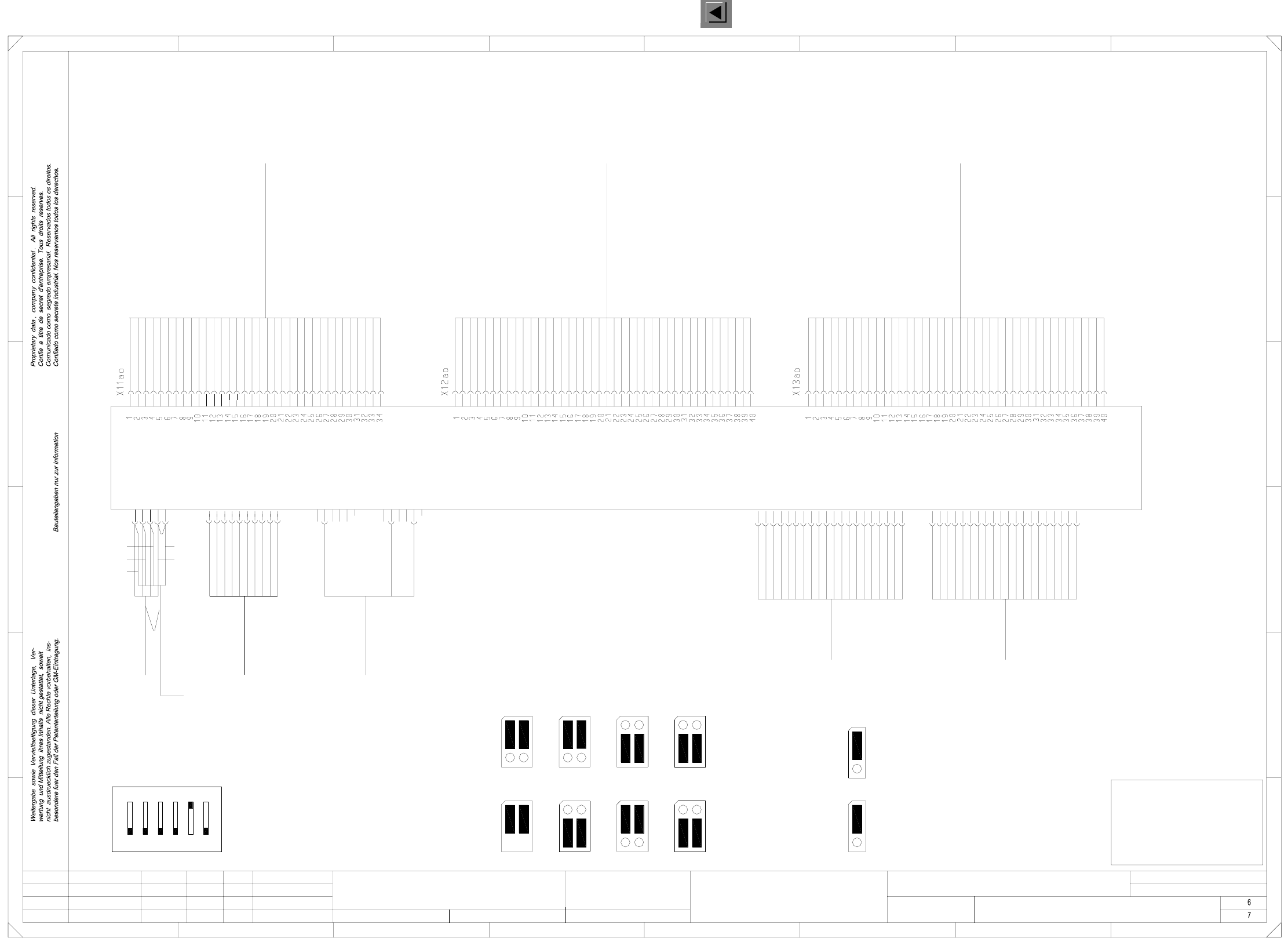
3 OPTIONS Circuit Diagrams 113
I
00119025-020101LD3 Dual conveyor, stationary side on the right,
wiring for control 1, TSP200 (Sh. 6 of 7)
Conveyor 1 plug X31am
Motor line, PCB conveyor
HS50 Conveyor 1
00351931
To conversion board
Conveyor 1 plug X32am
Sensor line 1, PCB conveyor
HS50 conveyor 1
00351932
Conveyor 1 plug X33am
To conversion board
Sensor line 2, PCB conveyor
HS50 conveyor 1
00351933
Stand.Status DateModified Name Orig. Repl. f. Replaced by
Check.
Date
Author
Sheet
Sh.
SMEMA
SiemensSiemens
J2
SMEMA
1
J2
1
Siemens
J1
1
J1
1
Siemens
1
SMEMA
J2
1
Error loop (Applies to 00349302 only)
J4
1
SMEMA
1
J1
Jumper settings
Error loop
J3
Input conveyor
J2
1
Output conveyor
1
J1
21
ON
6543
S1 address coding switch
TSP200
Motor + BB1
Motor - EB
Motor + EB
Motor - AB
Motor + AB
Motor + ZB
Motor - ZB
Motor - BB2
Motor + BB2
Motor - BB1
Motor B + BV
Motor B + BV
Motor A + BV
Motor A + BV
Motor A - BV
Motor A - BV
Motor B - BV
Motor B - BV
Bero BV
SB EB
GND
GND
+ 24 V
+ 24 V
SB ZB
SB AB
SB BB1
SB BB2
LS BB1 (res.)
LS BB2 (res.)
LS EB (res.)
LS ZB (res.)
LS AB (res.)
E4 (Opt.)
Bero HT 2 u
+ 24 V
GND
ESCH BRZ
Bero HT 1 o
Bero HT 1 u
Bero HT 2 o
ESCH BRA
E3 (Opt.)
Ventil ST BB1
Ventil ST BB2
Code 1 (Opt.)
Code 2 (Opt.)
Code 3 (Opt.)
Bero ST BB1
Bero ST BB2
SB UELP
E1 (Opt.)
E2 (Opt.)
Code 1 (Opt.)
Code 2 (Opt.)
Code 3 (Opt.)
E4 (Opt.)
E5 (Opt.)
E6 (Opt.)
A1 (Opt.)
A2 (Opt.)
A3 (Opt.)
E1 (Opt.)
E2 (Opt.)
E3 (Opt.)
VCC
E5 (Opt.)
E6 (Opt.)
A1 (Opt.)
A2 (Opt.)
A3 (Opt.)
GND
00348267 00348267 00348267
HT2o
SMD-Placement System Siplace HS50
Product status
Doc. status
Function status
To conversion board
Lifting table 2, top
Lifting table 2, bottom
ST
UELP
SB
HT2u
LS Light barrier
Excess length PCB
Stopper
Sonar prox. switch
Lifting table 1, bottom
Abbreviations
ESCH
BB2
EB
BRZ
BV
BRA
AB
BB1
HT1o
HT1u
E
A
Width narrower
Limit switch
Input conveyor
Width adjustment
Lifting table 1, top
Input
Placement sector 2
Width wider
Placement sector 1
Output conveyor
Output
(TSP200 or TSP200_M)
00349302 or 00353442
wh gnbn
ye ye
gn
bn
wh
ye
wh
bn
gn
n.c.
Dual conveyor, stationary side on the right
Wiring for control 1
10
9
234567
14
17
20
19
n.c.
n.c.
n.c.
6
5
4
7
10
9
n.c.
n.c.
n.c.
n.c.
n.c.
n.c.
n.c.
6
5
4
7
power supply
00352646
8
13
12
11
16
15
7
10
9
8
n.c.
n.c.
n.c.
n.c.
n.c.
n.c.
1 8
12345
X22ao
X21ao
Adapter cable:
3
2
1
6
5
4
18
X2ao
678
A
B
C
D
E
FF
E
D
C
B
3
2
X1ao
Interface preceding
machine
00303036
00303036
Interface succeeding
machine
V_GND_24VDC
V_+24VDC
V_SMEMA
V_Stoersign.
V_GND_24VDC
V_Erlaubnis
N_+24VDC
1
4
P5V
P24V
P40V
M digital
M
M
CANL
CANH
CAN-RES
n.c.
n.c.
n.c.
CAN bus
125kBits/s
00335323
Conveyor control, conveyor 1 ao
6
X6ao
3
2
1
4
Lifting table 2
5
6
M analog
Control:
Lifting table motors
00333592
Key
Key
X3ao
3
2
1
4
Lifting table 1
5
15.03.00
01
01
02
Ha
Ha
Ha
PL EA1 E
00119025-020101LD3
#
Haas
15.03.00
15.03.00
15.03.00
=
SIEMENS AG
+
FOR INFORMATION ONLY
This document will
not be replaced when
modifications are made!
16
15
14
17
20
19
18
N_SMEMA
N_GND_24VDC
N_Stoersign.
N_Abgegeben
n.c.
n.c.
V_Stoersign.
N_Stoersign.
n.c.
To plug X21ap
CAN-IR
n.c.
5 M analog
V_Angekommen
n.c.
n.c.
n.c.
n.c.
A
N_Anforderung
N_GND_24VDC
1
2
3
3
2
1
8
13
12
11
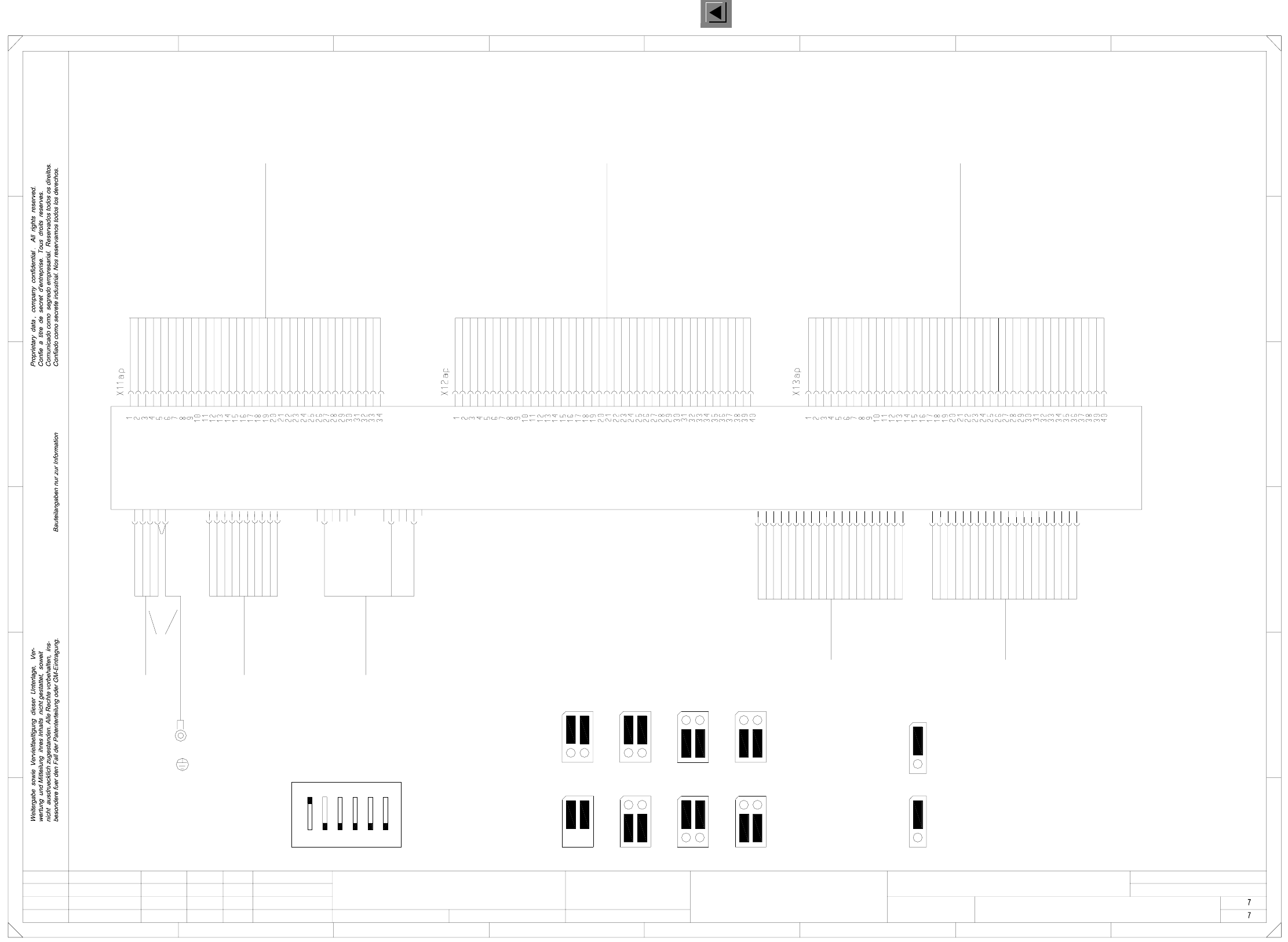
3 OPTIONS Circuit Diagrams 114
I
00119025-020101LD3 Dual conveyor, stationary side on the right,
wiring for control 2, TSP200 (Sh. 7 of 7)
=
SIEMENS AG
+
8
12345678
A
B
C
D
E
FF
X3ap
3
2
1
4
Lifting table 4
5
6
X6ap
n.c.
n.c.
n.c.
n.c.
n.c.
n.c.
n.c.
n.c.
n.c.
n.c.
n.c.
n.c.
n.c.
n.c.
n.c.
n.c.
3
2
1
4
Lifting table 3
5
6
M analog
Control:
lifting table motors
00333592
Key
Key
SMD-Placement System Siplace HS50
Product status
Doc. status
Function status
1x1.5mm² bk
Conveyor 2 plug X31an
To conversion board
Motor line, PCB conveyor
00353230
HS50 Conveyor 2
Conveyor 2 plug X32an
To conversion board
Sensor line 1 for PCB conveyor
HS50 Conveyor 2
00353231
Conveyor 2 plug X33an
To conversion board
HS50 Conveyor 2
Sensor line 2 for PCB conveyor
00353232
Stand.Status DateModified Name Orig. Repl. f. Replaced by
Check.
Date
Author
Sheet
Sh.
Lifting table 1, topHT1o
Lifting table 2, bottom
Lifting table 1, bottom
HT2o
ST
UELP
SB
HT2u
HT1u
LS
Lifting table 2, top
Excess length PCB
Stopper
Sonar prox. switch
Light barrier
Abbreviations
BB2
BRZ
BV
BRA
AB
BB1
ESCH
EB
E
A
Placement sector 2
Width narrower
Width adjustment
Width wider
Limit switch
Input conveyor
Input
Placement sector 1
Output conveyor
Output
Motor - BB1
Motor + BB2
Motor - BB2
Motor - ZB
Motor + ZB
Motor + AB
Motor - AB
Motor + EB
Motor - EB
Motor + BB1
Motor B - BV
Motor B - BV
Motor A - BV
Motor A - BV
Motor A + BV
Motor A + BV
Motor B + BV
Motor B + BV
LS AB (res.)
LS ZB (res.)
LS EB (res.)
LS BB2 (res.)
LS BB1 (res.)
SB BB2
SB BB1
SB AB
SB ZB
+ 24 V
+ 24 V
SB EB
Bero BV
GND
GND
E4 (Opt.)
Bero HT 2 u
ESCH BRA
Bero HT 2 o
Bero HT 1 u
Bero HT 1 o
ESCH BRZ
+ 24 V
GND
E3 (Opt.)
E2 (Opt.)
E1 (Opt.)
A3 (Opt.)
A2 (Opt.)
A1 (Opt.)
E6 (Opt.)
E5 (Opt.)
E4 (Opt.)
Code 3 (Opt.)
Code 2 (Opt.)
Code 1 (Opt.)
E2 (Opt.)
E1 (Opt.)
SB UELP
Bero ST BB2
Bero ST BB1
Code 3 (Opt.)
Code 2 (Opt.)
Code 1 (Opt.)
Ventil ST BB2
Ventil ST BB1
E3 (Opt.)
A3 (Opt.)
A2 (Opt.)
A1 (Opt.)
E6 (Opt.)
E5 (Opt.)
VCC
GND
(TSP200 or TSP200_M)
00349302 or 00353442
Jumper settings
1
14
17
20
19
18
X2ap
X1ap
Interface preceding
machine
00303036
00303036
Interface succeeding
machine
V_GND_24VDC
V_+24VDC
V_SMEMA
E
D
C
B
A
N_Abgegeben
N_Anforderung
6
5
4
7
10
9
8
13
12
11
16
15
14
17
20
19
n.c.
n.c.
n.c.
n.c.
n.c.
Dual conveyor, stationary side on the right
Wiring for control 2
10
9
234567
7
10
9
8
3
2
1
4
P5V
P24V
P40V
M digital
M
M
CANL
CANH
V_Stoersign.
V_GND_24VDC
V_Angekommen
V_Erlaubnis
N_+24VDC
N_SMEMA
N_GND_24VDC
N_Stoersign.
Additional ground
N_GND_24VDC
V_Stoersign.
N_Stoersign.
n.c.
n.c.
n.c.
18
3
2
1
6
5
4
7
power supply
00352646
8
13
12
11
16
15
CAN-RES
n.c.
n.c.
n.c.
CAN-IR
n.c.
5 M analog
Mounting plate
PCB conveyor HS50
3
2
1
CAN bus
125kBits/s
00335323
X22ap
X21ap
Adapter cable for
3
2
1
6
5
4
01
01
02
Ha
Ha
Ha
Conveyor control, conveyor 2 ap
PL EA1 E
00119025-020101LD3
#
Haas
15.03.00
15.03.00
15.03.00
15.03.00
21
ON
3456
S1 address coding switch
Siemens
SMEMA
Input conveyor
Siemens
J2
1
SMEMA
J2
1
J2
1
Output conveyor
1
J1
Siemens
J1
1
J1
1
Siemens
SMEMA
J2
1
SMEMA
1
J1
1
Error loop (Applies to 00349302 only)
J4
1
Error loop
J3
TSP200
wh
bn
gn
gn
wh
bn
ye
ye