YAMAHA-YG系列 换螺杆指导书 - 第5页
Service Engineer Service I nformati on SI080 2008 E-000 = YG series: Replacement proc edure for ball screws of each axis 5/65 1. Remove the bolts that secure the SLEEVE BRG. When remov ing the ball screw of YGD ,YG88, …
Service Engineer
Service Information
SI0802008E-000= YG series: Replacement procedure for ball screws of each axis
4/65
1.2. How to remove the ball screw of X-axis
Caution:
As some removed parts may contain shims, please be careful not to lose them. Also, please note
down the places where the shims were set.
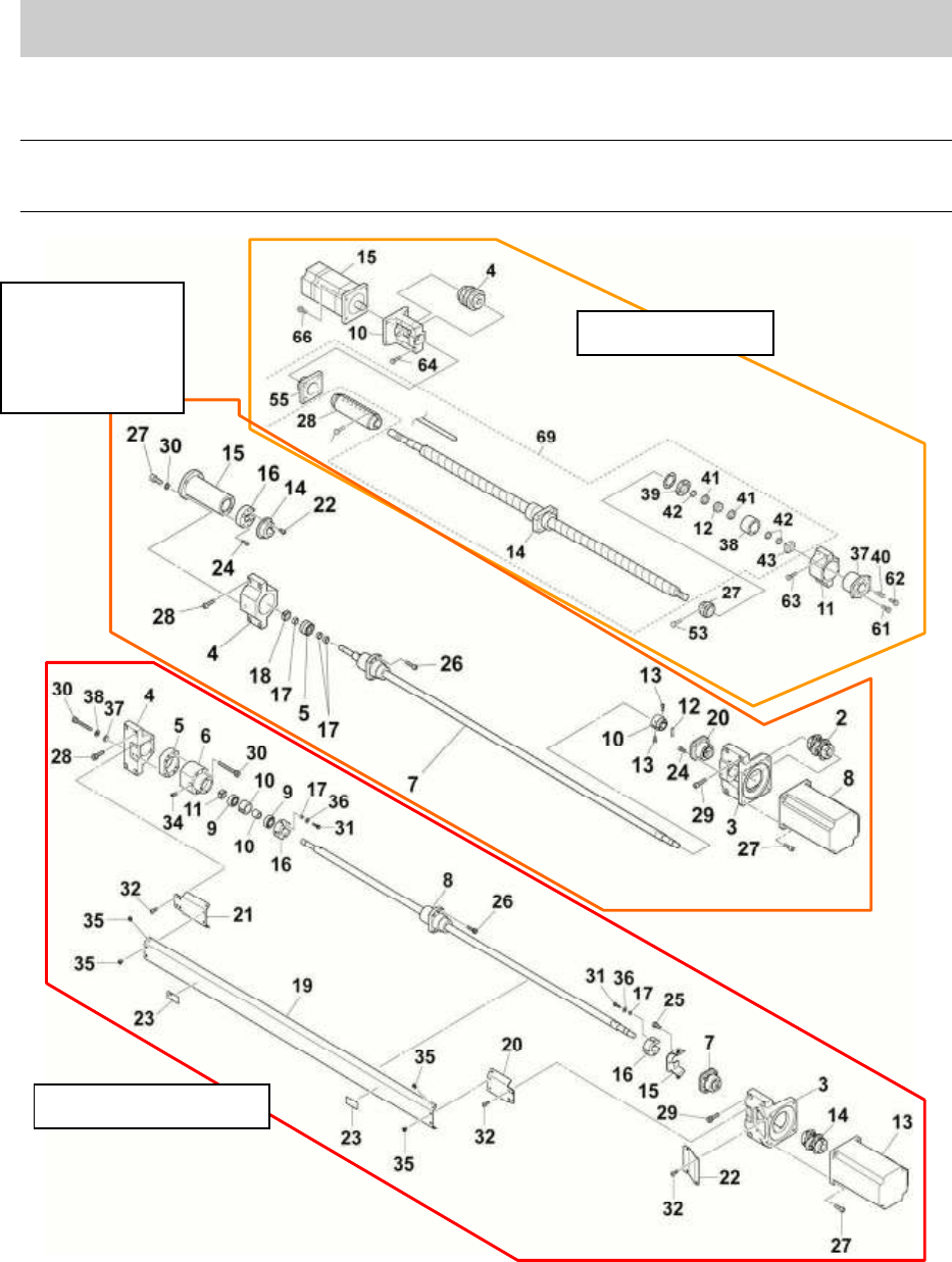
Figure 1
YGD & Xg
YG100
YG88
YG200(L)
YG300
YG100R & YG88R
Service Engineer
Service Information
SI0802008E-000= YG series: Replacement procedure for ball screws of each axis
5/65
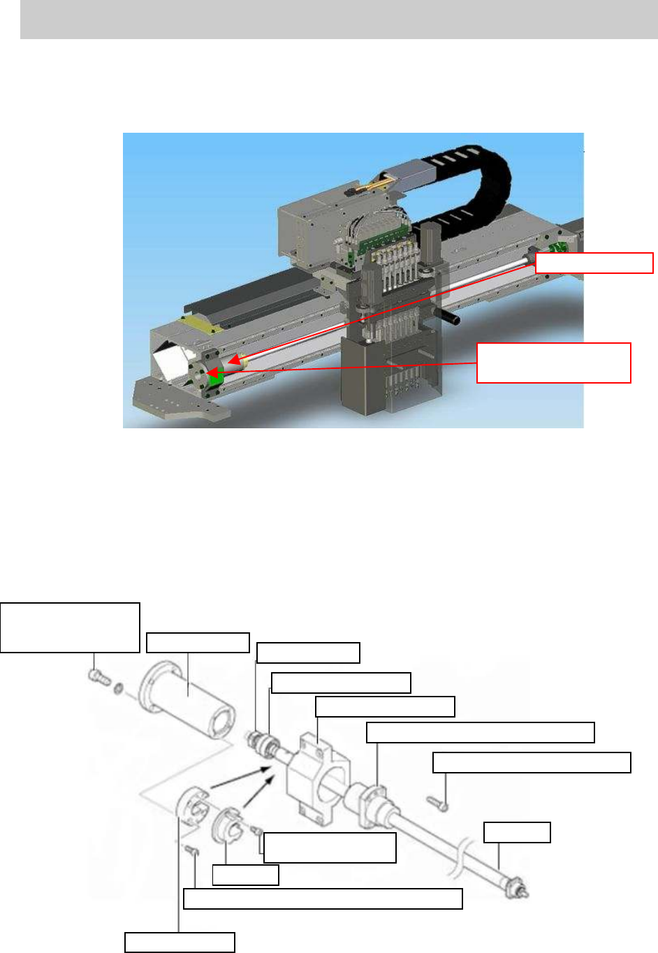
1. Remove the bolts that secure the SLEEVE BRG.
When removing the ball screw of YGD,YG88, YG100, YG200(L) and YG300 machines
1) Remove the four bolts (M5*14) that secure the SLEEVE BRG.
(YG88,YG100, YG200(L) and YG300:No.15 / YGD: No.37 in Figure 1).
Figure 2
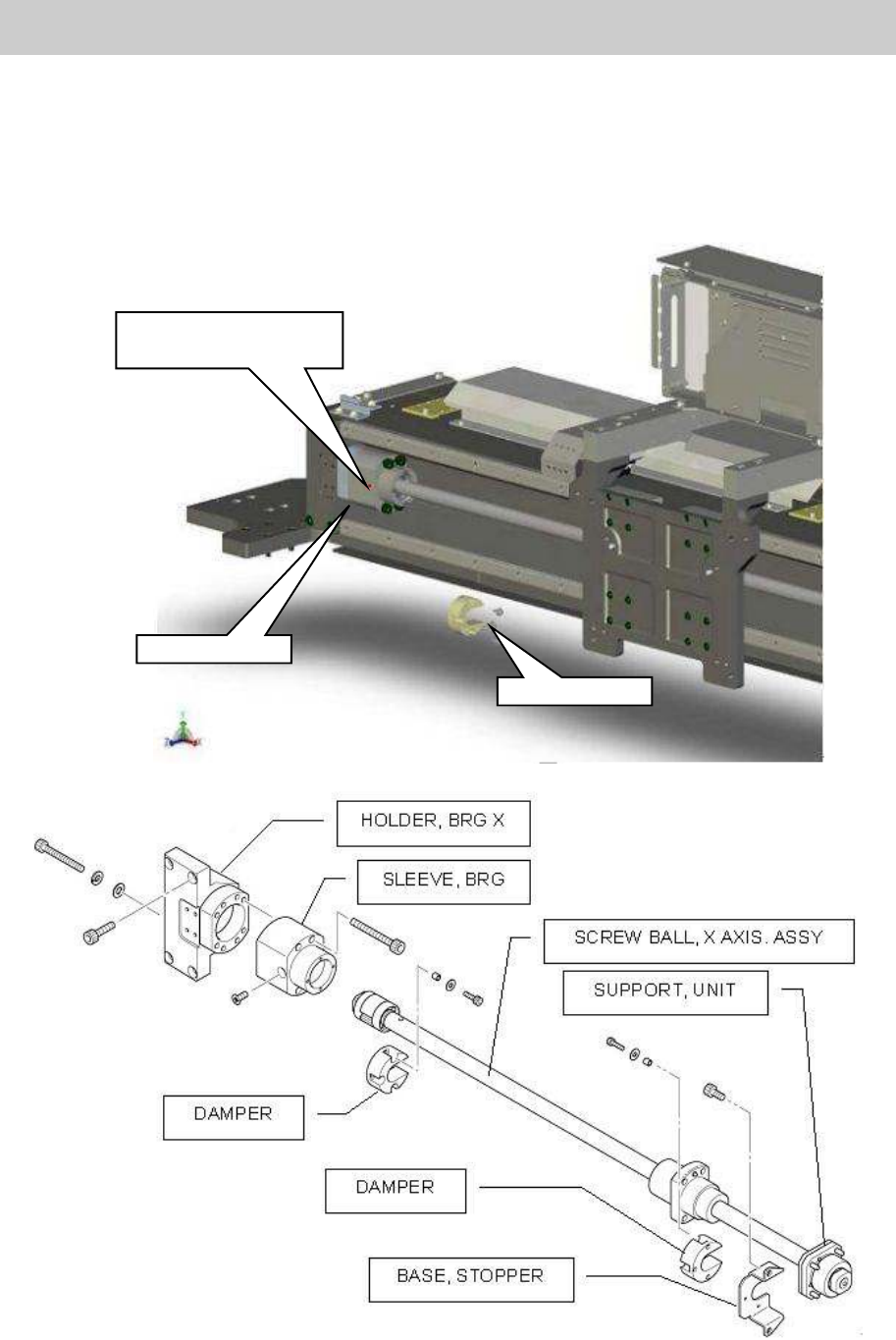
2) Remove the fixing bolts that secure the DAMPER with a hex wrench (Size 3) and remove the
DAMPER.
3) Remove the bolts to fix the COVER, BRG with a hex wrench (Size 3) and remove the
COVER, BRG.
4) Remove the SLEEVE, BRG.
* When the SLEEVE, BRG cannot be removed because of the cable duct, remove the bolts
that secure the stay plate and move the plate to the position where the SLEEVE, BRG can be
removed.
.
Figure 3
Sleeve BRG
Four bolts for fixing
the SLEEVE BTG
Bolts for fixing the
SLEEVE, BRG
(Qty:4)
SLEEVE, BRG
Square nut
BRG, ANGULAR
HOLDER, BRG X
Nut bearing (SCREW BALL X AXIS)
BOLT HEX, SOCKET HEAD
DAMPER
Bolts for fixing the
DAMPER(Qty:2)
DAMPER
Bolts for fixing the COVER, BRG (Qty:4)
COVER, BRG
Service Engineer
Service Information
SI0802008E-000= YG series: Replacement procedure for ball screws of each axis
6/65
When removing the ball screw of YG88R and YG100R
1) Remove the cover of the ball screw consists of three pieces (in the middle and the both
side/COVER, X AXIS) with a screwdriver.
2) Remove the three bolts that secure the DAMPER to remove it from the near side.
3) Remove the four bolts that secure the SLEEVE, BRG, then loosen the SCREW, FLAT
HEAD for the SPACER, BRG SET to move the SLEEVE, BRG to the right.
Figure 4
DAMPER
SLEEVE, BRG
The detent bolt for the
SPACER, BRG SET