4OM-1011-002.pdf - 第100页
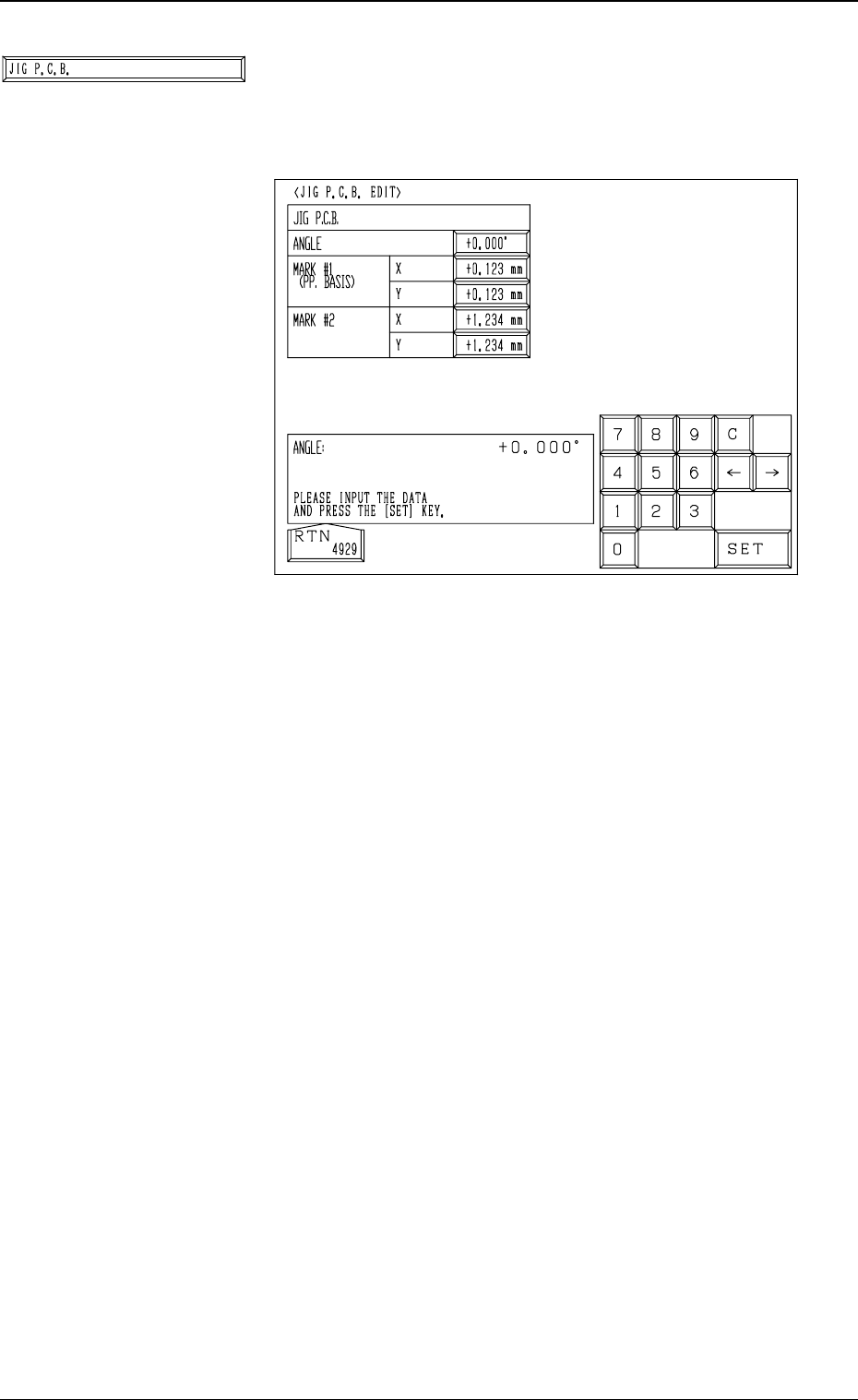
0305-001 Tg0860-PM-MM *6 [JIG P .C.B.] Key When this key is pressed, the “JIG P .C.B. EDIT” display (Fig. 3.32) appears on the screen, enabling the entry of pa- rameters related to the jig P .C.B. • A parameter can be en…
0305-001 Tg0860-PM-MM
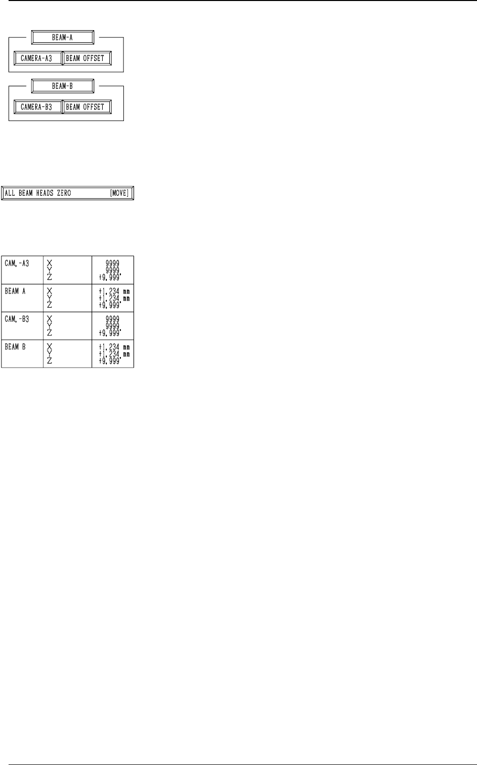
*3 [CAMERA-A3] and [BEAM OFFSET] Keys in “BEAM-
A” Group Box and [CAMERA-B3] and [BEAM OFFSET]
Keys in “BEAM-B” Group Box
The machine performs the offset teaching operation for each
individual units (devices).
When one of the above-described keys is selected and the
[MOVE] button is pressed, the machine starts teaching the
offset data related to the selected unit (device).
Note: Before performing any teaching operation, position
the jig P.C.B. and zero both beams.
*4 [ALL BEAM HEADS ZERO [MOVE]] Key
Both Beams A and B are zeroed.
When this key is selected and the [MOVE] button is pressed,
the zeroing operation starts.
*5 The following offset values are shown.
• Offset Values for Beam A:
“X (Horizontal)”, “Y (Vertical)”, and “Z (Theta)”
• Offset Values for Beam B:
“X (Horizontal)”, “Y (Vertical)”, and “Z (Theta)”
• Offset Values for Camera-A3 (P.E.C. Camera A3):
“Z (Theta)”
• Offset Values for Magnification of Camara-A3:
“X (Horizontal)” and “Y (Vertical)”
• Offset Values for Camera-B3 (P.E.C. Camera B3):
“Z (Theta)”
• Offset Values for Magnification of Camera-B3:
“X (Horizontal)” and “Y (Vertical)”
3-48
6.1 P.E.C. RECOG CAMERA & BEAM OFFSET (STEP-1) Display
Fig. 4C59
Fig. 4C60
Fig. 4C61
0305-001 Tg0860-PM-MM
*6 [JIG P.C.B.] Key
When this key is pressed, the “JIG P.C.B. EDIT” display
(Fig. 3.32) appears on the screen, enabling the entry of pa-
rameters related to the jig P.C.B.
• A parameter can be entered in each data box.
The parameters (X and Y) for “MARK #1 (PP. BA-
SIS)” are the coordinates (distances) based on the refer-
ence point for P.C.B. positioning.
Enter the numeric values described on the jig P.C.B.
3-49
6.1 P.E.C. RECOG CAMERA & BEAM OFFSET (STEP-1) Display
Fig. 4C63
Fig. 4C62
0305-001 Tg0860-PM-MM
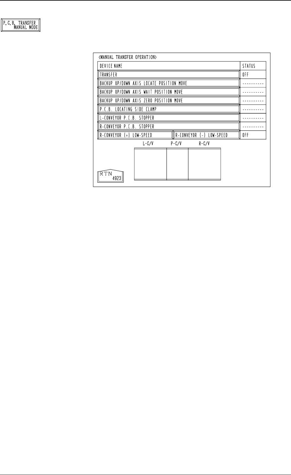
*7 [P.C.B. TRANSFER MANUAL MODE] Key
When this key is pressed, the “MANUAL TRANSFER
OPERATION” display (Fig. 4C65) appears on the screen.
The selected device can be moved manually.
When the [P.C.B. TRANSFER MANUAL MODE] key
is selected and the [MOVE] button is pressed, the se-
lected device is activated.
• [TRANSFER] Key:
A series of P.C.B. transfer and positioning operations
are performed.
• [BACKUP UP/DOWN AXIS LOCATE POSITION
MOVE] Key:
The P.C.B. backup base moves to the positioning spot.
• [BACKUP UP/DOWN AXIS WAIT POSITION MOVE]
Key:
The P.C.B. backup base moves to the standby position.
• [BACKUP UP/DOWN AXIS ZERO POSITION
MOVE] Key:
The P.C.B. backup base moves to its origin.
• [P.C.B. LOCATING SIDE CLAMP] Key:
The P.C.B. locating side clamp moves forward and back-
ward.
• [L-CONVEYOR P.C.B. STOPPER] Key:
The L-conveyor P.C.B. stopper moves forward and back-
ward.
• [R-CONVEYOR P.C.B. STOPPER] Key:
The R-conveyor P.C.B. stopper moves forward and back-
ward.
• [P-CONVEYOR (+) LOW-SPEED] Key:
The P conveyor moves forward (normal rotation) at low
speed.
• [P-CONVEYOR (-) LOW-SPEED] Key:
The P conveyor moves backward (reverse rotation) at
low speed.
3-50
6.1 P.E.C. RECOG CAMERA & BEAM OFFSET (STEP-1) Display
Fig. 4C65
Fig. 4C64