4OM-1011-002.pdf - 第103页
0305-001 Tg0860-PM-MM *9 [GAIN ・ LEVEL] Key When this key is pressed, the following display appears on the screen. These parameters are used to set amplifications at which the image signals of the image taken by the comp…
0305-001 Tg0860-PM-MM
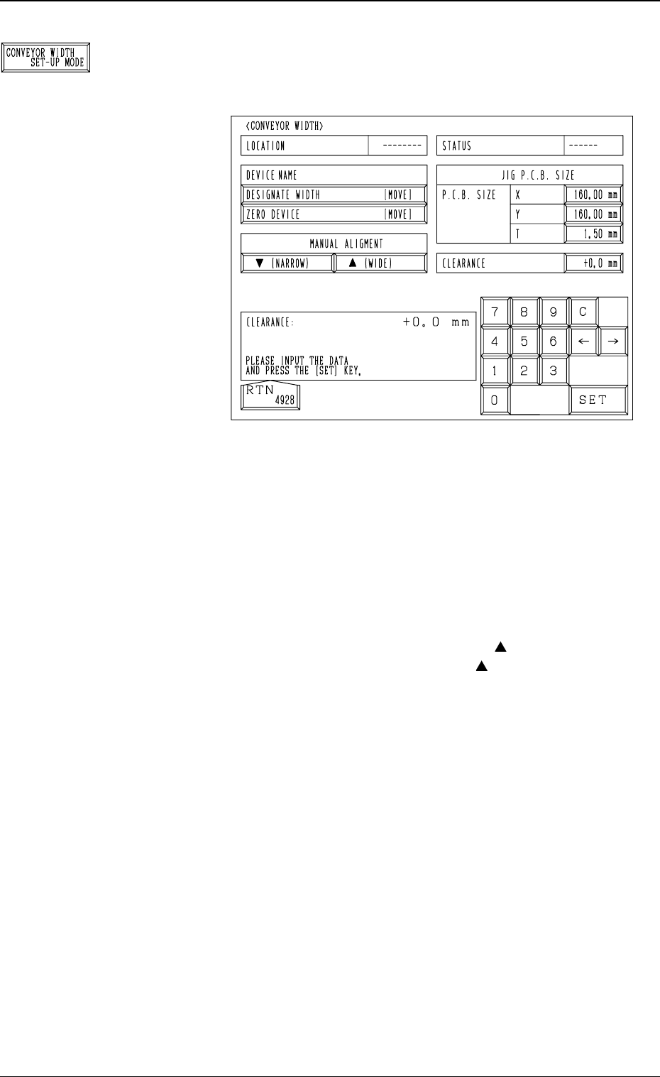
*8 [CONVEYOR WIDTH SET-UP MODE] Key
When this key is pressed, the following display (Fig. 4C67)
appears on the screen.
The conveyor width can be changed.
• P.C.B. SIZE X, Y, and T : Enter the dimensions of the
jig P.C.B. in these data boxes.
Normal Settings: X = 160 mm,
Y = 160 mm, and T = 1.50
mm
• CLEARANCE : Enter a clearance of the conveyor width
in relation to the jig P.C.B. size.
• MANUAL ALIGNMENT : When the [ (NARROW)]
or the [ (WIDE)] key is
selected and the [MOVE]
button is pressed, the con-
veyor width is narrowed or
widened.
• When the [ZERO DEVICE [MOVE]] key is selected
and the [MOVE] button is pressed, the conveyor width
variable shaft is zeroed.
Ref.: Before the zeroing operation is initiated, each con-
veyor is automatically activated to check that no
P.C.B. is located at any irregular position.
• When the [DESIGNATE WIDTH [MOVE]] key is se-
lected and the [MOVE] button is pressed, activate the
conveyor automatically to check that no P.C.B. is located
at any irregular position and then set up the conveyor
width to “JIG P.C.B. SIZE + CLEARANCE”.
Ref.: It is checked that no P.C.B. is located at any ir-
regular position when the set-up operation is per-
formed for the first time after the “CONVEYOR
WIDTH” display is opened.
It is not checked when the second or the subse-
quent set-up operation is performed.
3-51
6.1 P.E.C. RECOG CAMERA & BEAM OFFSET (STEP-1) Display
Fig. 4C67
Fig. 4C66
0305-001 Tg0860-PM-MM
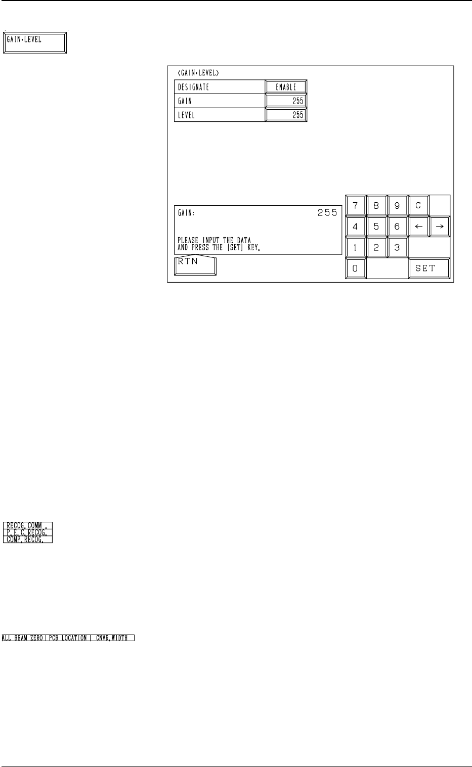
*9 [GAIN・LEVEL] Key
When this key is pressed, the following display appears on the screen.
These parameters are used to set amplifications at which the image
signals of the image taken by the component recognition camera is
converted into the picture information representing brightness.
Parameters are set as the offset values for camera reference gain and
level.
Normal Fixed Value: ± 0
• When “ENABLE” is set in the “DESIGNATE” data box, be sure to
set parameters in the “GAIN” and “LEVEL” data boxes.
The set parameters are used for P.E.C. recognition.
When “DISABLE” is set in the data box, the standard parameters
are set in the “GAIN” and “LEVEL” data boxes.
• The lower the gain is, the bigger the contrast becomes.
• The lower the level is, the brighter the whole view becomes.
Note: Teaching operations are performed through P.E.C. recogni-
tion.
Incorrect gain and level parameters lead to the adverse result
of teaching operations, causing some trouble.
*10 RECOG. COMM.
When “DISABLE” is set in the “P.E.C.” and “COMPONENT REC-
OGNITION” data boxes at the “TEST MODE” display, the back-
ground color of “P.E.C. RECOG.” and “COMP. RECOG.” becomes
light red. (No background color in normal cases)
Note: In this case, the recognition processing is not made even if
the teaching operations are performed. Therefore, the results
of various teaching operations are not reflected on the offset
data.
*11 Set State Indications
When the set-up operations for “ALL BEAM ZERO”, “PCB LO-
CATION”, and “CNVR. WIDTH” are completed, the background
color turns green. Otherwise, the background has no color.
Note: When each unit (device) is not set up and the teaching
operations are performed, the offset values may not be
taught correctly.
Before performing the teaching operations, be sure to zero
Beams A and B, position the jig P.C.B., and set up the
conveyor width.
3-52
6.1 P.E.C. RECOG CAMERA & BEAM OFFSET (STEP-1) Display
Fig. 4C69
Fig. 4C68
Fig. 4C70
Fig. 4C71

0305-001 Tg0860-PM-MM
Operation Procedure
• Required Item
Special Jig P.C.B. (Option): P.C.B. Recognition Calibration Jig (JG-0086)
(1) Check the followings.
• Check that the machine is powered.
• Check that the supply cover is completely closed.
(2) Set “PLACE REF.” in the “P.C.B. LOCATE MODE” data box at the
“P.C.B. TRANSFER MODE SET-UP” Display. (Hierarchical Sequence:
“DATA EDIT” Display → “DEVICE DATA” Display → “P.C.B.
TRANSFER MODE SET-UP” Display)
(3) Set parameters in the data boxes related to the special jig P.C.B. (option)
at the “JIG P.C.B. EDIT” display. Hierarchical Sequence: “SPECIAL
SEL.” Display → “TEACH OFFSET” Display → “P.E.C. RECOG CAM-
ERA & BEAM OFFSET (STEP-1)” Display → “JIG P.C.B. EDIT” Dis-
play)
Enter the numerical values related to the mark on the P.C.B. positioning
reference side in the “X” and “Y” data boxes of the label “MARK #1
(PP. BASIS)”.
(4) Detach the P.C.B. support pins at the “PCB SUPPORT PINS SET-UP
MODE” display. (Hierarchical Sequence: “MANUAL MODE” Display
→ “PCB SUPPORT PINS SET-UP MODE” Display)
(5) Set “160 mm” in the “X” and “Y” data boxes of the label “P.C.B. SIZE”
at the “CONVEYOR WIDTH” display. Then, select the [DESIGNATE
WIDTH [MOVE]] key and press the [MOVE] button.
(6) Attach the P.C.B. support pins at the “PCB SUPPORT PINS SET-UP
MODE” display. (Hierarchical Sequence: “MANUAL MODE” Display
→ “PCB SUPPORT PINS SET-UP MODE” Display)
(7) Press the [TRANSFER] key at the “P.C.B. TRANSFER OPERATION”
display to position the jig P.C.B.
Use the menus at the “PCB SUPPORT PINS SET-UP MODE” display
to confirm that the jig P.C.B. is securely fixed.
(8) Select the [ALL BEAM HEADS ZERO [MOVE]] key and press the
[MOVE] button to zero all beam heads.
(9) To specify the gain and level, use the “GAIN・LEVEL” display.
Note: In normal cases, set “DISABLE” in the “DESIGNATE” data box.
(10) Select the item to be taught and press the [MOVE] button.
The machine starts the teaching operation (automatic).
3-53
6.1 P.E.C. RECOG CAMERA & BEAM OFFSET (STEP-1) Display