4OM-1011-002.pdf - 第106页
0305-001 Tg0860-PM-MM Special Jig (Option) Notes: (a ) Consult our sales personnel for the detailed in- formation on how to use the special jig compo- nent. (b) Handle this fragile jig very carefully . Name : Component R…
0305-001 Tg0860-PM-MM
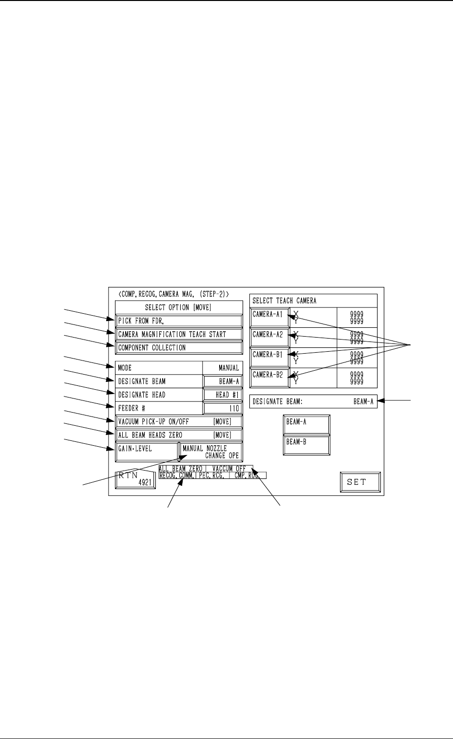
6.2 COMP. RECOG. CAMERA MAG. (STEP-2) Display
• This display allows teaching the magnification of the component recognition
camera.
The offset values are calculated by recognizing the printed pattern on the
special jig (option) picked up by a nozzle with the component recognition
camera.
Note: (a) A special jig (option) is required.
The parameters are factory-set at shipment. Normally, it is not nec-
essary to teach these parameters.
(b) Follow the teaching procedures in the specified order. Otherwise,
some trouble (such as inaccurate component placement, frequent
mechanical errors, etc.) will arise.
When the [COMPONENT RECOG CAMERA MAGNIFICATION (STEP-
2)] key is pressed at the “TEACH OFFSET” display, the following display
appears on the screen.
*12
*13
*15
*14
*1
*2
*3
*4
*5
*6
*7
*8
*9
*10
*11
3-54
6.2 COMP. RECOG. CAMERA MAG. (STEP-2) Display
Fig. 4C72
0305-001 Tg0860-PM-MM
Special Jig (Option)
Notes: (a) Consult our sales personnel for the detailed in-
formation on how to use the special jig compo-
nent.
(b) Handle this fragile jig very carefully.
Name : Component Recognition Calibration Jig
Model Name : JG-0084
Dimensions : Approx. 50 (width) × 50 (depth) × 1.5 mm
(thickness)
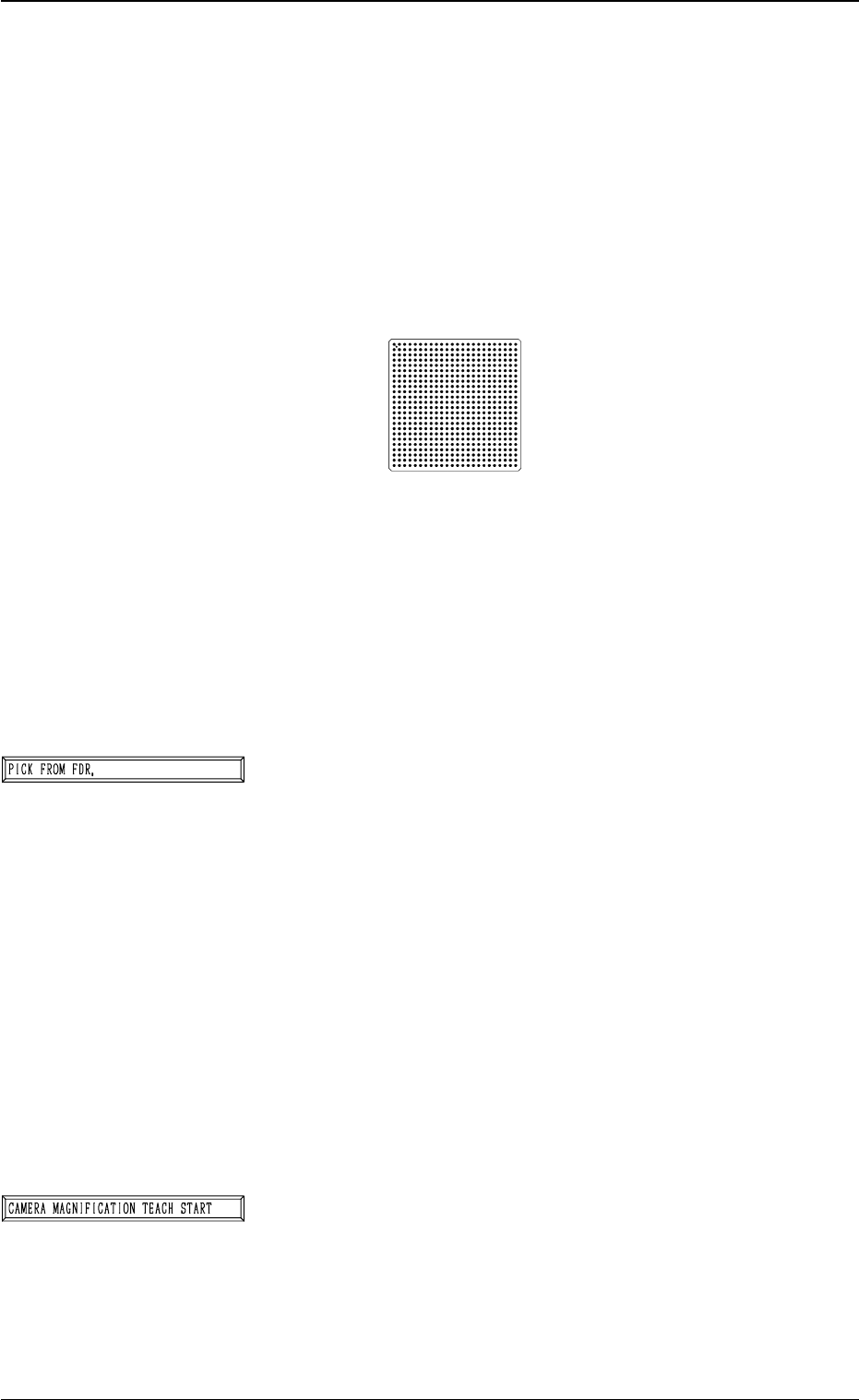
• The jig component has a pattern of round marks printed on
the opal glass, forming a grid (matrix) and the pattern is
used to calculate the magnification.
• Only the “MF01”, “MF02” or “MA06” must be used to pick
up this special jig.
• The jig must be attached to or detached from the nozzle by
hand.
*1 [PICK FROM FDR.] Key
The machine works to pick up the special jig.
When this key is selected and the [MOVE] button is pressed,
the machine performs the pick-up operations.
The head moves down to the pick-up point over the desig-
nated feeder and stops.
The [VACUUM PICK-UP ON/OFF [MOVE]] key must
be selected and the [MOVE] button must be pressed to
turn on the vacuum. Then, the special jig must be attached
to the head by hand with the printed mark side facing down-
ward.
Note: When the special jig must be attached to the head
by hand, special care is required for safety pur-
poses because the operator has to put part of his/
her body inside the machine.
*2 [CAMERA MAGNIFICATION TEACH START] Key
The machine works to teach the magnification of the se-
lected component recognition camera.
When this key is selected and the [MOVE] button is pressed,
the machine starts the teaching operation.
Note: Before performing the teaching operations, be sure
to make the nozzle pick up the special jig and zero
both beams.
3-55
6.2 COMP. RECOG. CAMERA MAG. (STEP-2) Display
Fig. 4C73
Fig. 4C74
Fig. 4C75
0305-001 Tg0860-PM-MM
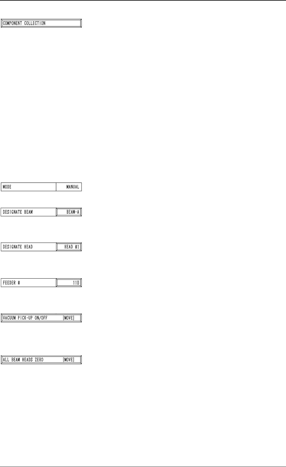
*3 [COMPONENT COLLECTION] Key
The machine works to collect the picked special jig.
When this key is selected and the [MOVE] button is pressed,
the machine starts to collect the special jig.
Note: Perform this collection operation after the teaching
operation is completed.
The head moves down to the pick-up point over the desig-
nated feeder and stops.
The [VACUUM PICK-UP ON/OFF [MOVE]] key must
be selected and the [MOVE] button must be pressed to
turn off the vacuum. Then, the jig component must be col-
lected.
(Be sure not to drop the jig component. Otherwise, it may
break because it is very fragile.)
Note: When the special jig must be collected by hand,
special care is required for safety purposes because
the operator has to put part of his/her body inside
the machine.
*4 MODE
Only “MANUAL” is available.
*5 DESIGNATE BEAM
Designate the beam to be used to pick up the special jig.
Set either “BEAM-A” or “BEAM-B” in the data box.
*6 DESIGNATE HEAD
Designate the head to be used to pick up the special jig.
Set either “HEAD #1” or “HEAD #2” in the data box.
*7 FEEDER #
The head moves to the feeder designated when the special
jig is picked up or collected.
*8 [VACUUM PICK-UP ON/OFF [MOVE]] Key
The vacuum can be turned on or off.
When this key is selected and the [MOVE] button is pressed,
the vacuum is turned ON or OFF.
*9 [ALL BEAM HEADS ZERO [MOVE]] Key
Both Beams A and B are zeroed.
When this key is selected and the [MOVE] button is pressed,
the zeroing operation starts.
3-56
6.2 COMP. RECOG. CAMERA MAG. (STEP-2) Display
Fig. 4C76
Fig. 4C77
Fig. 4C78
Fig. 4C79
Fig. 4C80
Fig. 4C81
Fig. 4C82