4OM-1011-002.pdf - 第107页
0305-001 Tg0860-PM-MM *3 [COMPONENT COLLECTION] Key The machine works to collect the picked special jig. When this key is selected and the [MOVE] button is pressed, the machine starts to collect the special jig. Note: Pe…
0305-001 Tg0860-PM-MM
Special Jig (Option)
Notes: (a) Consult our sales personnel for the detailed in-
formation on how to use the special jig compo-
nent.
(b) Handle this fragile jig very carefully.
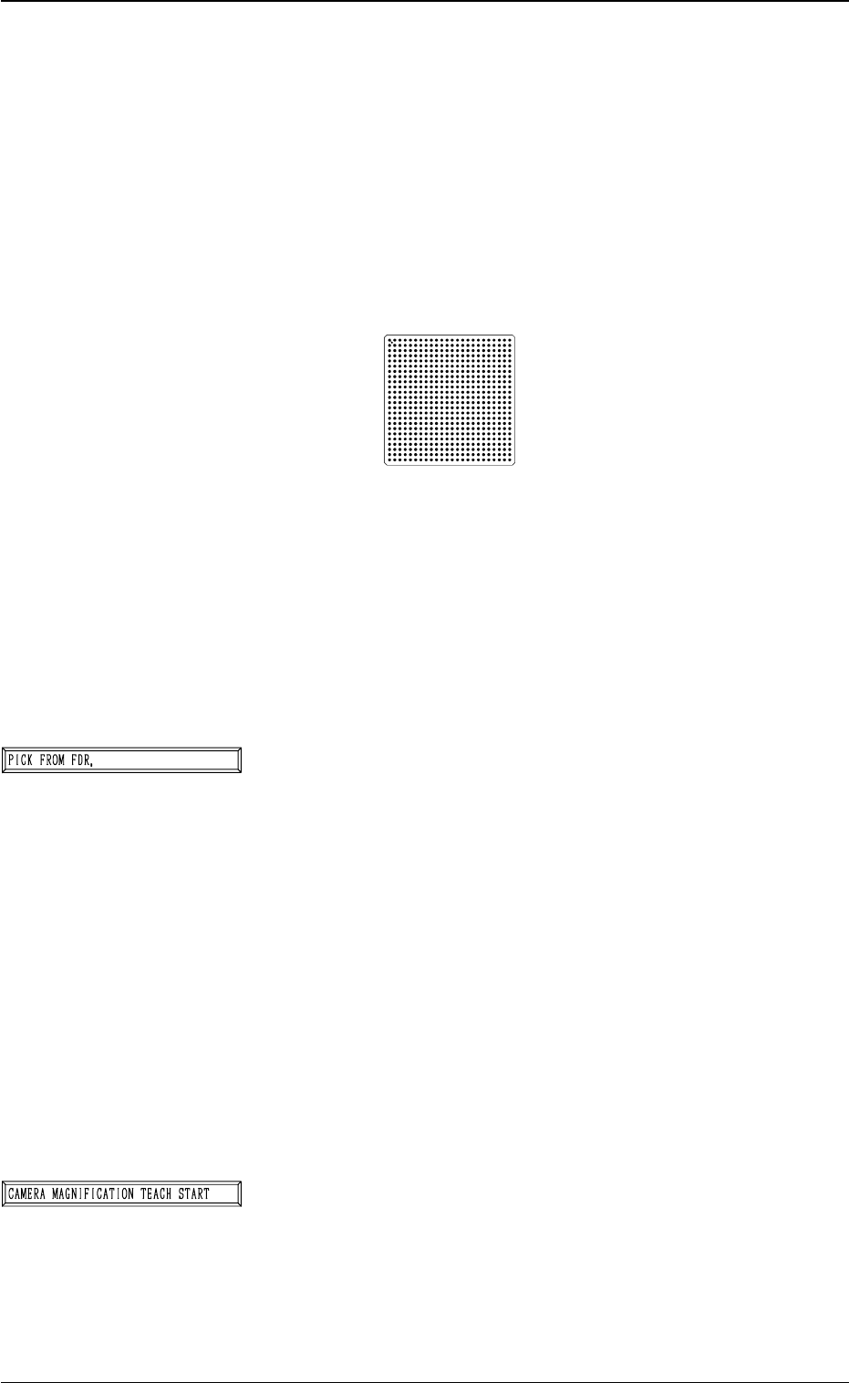
Name : Component Recognition Calibration Jig
Model Name : JG-0084
Dimensions : Approx. 50 (width) × 50 (depth) × 1.5 mm
(thickness)
• The jig component has a pattern of round marks printed on
the opal glass, forming a grid (matrix) and the pattern is
used to calculate the magnification.
• Only the “MF01”, “MF02” or “MA06” must be used to pick
up this special jig.
• The jig must be attached to or detached from the nozzle by
hand.
*1 [PICK FROM FDR.] Key
The machine works to pick up the special jig.
When this key is selected and the [MOVE] button is pressed,
the machine performs the pick-up operations.
The head moves down to the pick-up point over the desig-
nated feeder and stops.
The [VACUUM PICK-UP ON/OFF [MOVE]] key must
be selected and the [MOVE] button must be pressed to
turn on the vacuum. Then, the special jig must be attached
to the head by hand with the printed mark side facing down-
ward.
Note: When the special jig must be attached to the head
by hand, special care is required for safety pur-
poses because the operator has to put part of his/
her body inside the machine.
*2 [CAMERA MAGNIFICATION TEACH START] Key
The machine works to teach the magnification of the se-
lected component recognition camera.
When this key is selected and the [MOVE] button is pressed,
the machine starts the teaching operation.
Note: Before performing the teaching operations, be sure
to make the nozzle pick up the special jig and zero
both beams.
3-55
6.2 COMP. RECOG. CAMERA MAG. (STEP-2) Display
Fig. 4C73
Fig. 4C74
Fig. 4C75
0305-001 Tg0860-PM-MM
*3 [COMPONENT COLLECTION] Key
The machine works to collect the picked special jig.
When this key is selected and the [MOVE] button is pressed,
the machine starts to collect the special jig.
Note: Perform this collection operation after the teaching
operation is completed.
The head moves down to the pick-up point over the desig-
nated feeder and stops.
The [VACUUM PICK-UP ON/OFF [MOVE]] key must
be selected and the [MOVE] button must be pressed to
turn off the vacuum. Then, the jig component must be col-
lected.
(Be sure not to drop the jig component. Otherwise, it may
break because it is very fragile.)
Note: When the special jig must be collected by hand,
special care is required for safety purposes because
the operator has to put part of his/her body inside
the machine.
*4 MODE
Only “MANUAL” is available.
*5 DESIGNATE BEAM
Designate the beam to be used to pick up the special jig.
Set either “BEAM-A” or “BEAM-B” in the data box.
*6 DESIGNATE HEAD
Designate the head to be used to pick up the special jig.
Set either “HEAD #1” or “HEAD #2” in the data box.
*7 FEEDER #
The head moves to the feeder designated when the special
jig is picked up or collected.
*8 [VACUUM PICK-UP ON/OFF [MOVE]] Key
The vacuum can be turned on or off.
When this key is selected and the [MOVE] button is pressed,
the vacuum is turned ON or OFF.
*9 [ALL BEAM HEADS ZERO [MOVE]] Key
Both Beams A and B are zeroed.
When this key is selected and the [MOVE] button is pressed,
the zeroing operation starts.
3-56
6.2 COMP. RECOG. CAMERA MAG. (STEP-2) Display
Fig. 4C76
Fig. 4C77
Fig. 4C78
Fig. 4C79
Fig. 4C80
Fig. 4C81
Fig. 4C82
0305-001 Tg0860-PM-MM
*10 [GAIN・LEVEL] Key
When this key is pressed, the “GAIN・LEVEL” display (Fig.
4C69) appears on the screen.
These parameters are used to set amplifications at which
the image signals of the image taken by the component rec-
ognition camera is converted into the picture information
representing brightness.
Parameters are set as the offset values for camera refer-
ence gain and level.
Normal Fixed Value: ± 0
• When "ENABLE” is set in the “DESIGNATE” data box
at the “GAIN・LEVEL” display, be sure to set param-
eters in the “GAIN” and “LEVEL” data boxes. The set
parameters are used for P.E.C. recognition.
When “DISABLE” is set in the data box, the standard
parameters are set in the “GAIN” and “LEVEL” data
boxes.
• The lower the gain is, the bigger the contrast becomes.
• The lower the level is, the brighter the whole view be-
comes.
Note: Teaching operations are performed through com-
ponent recognition.
Incorrect gain and level parameters lead to the ad-
verse result of teaching operations, causing some
trouble.
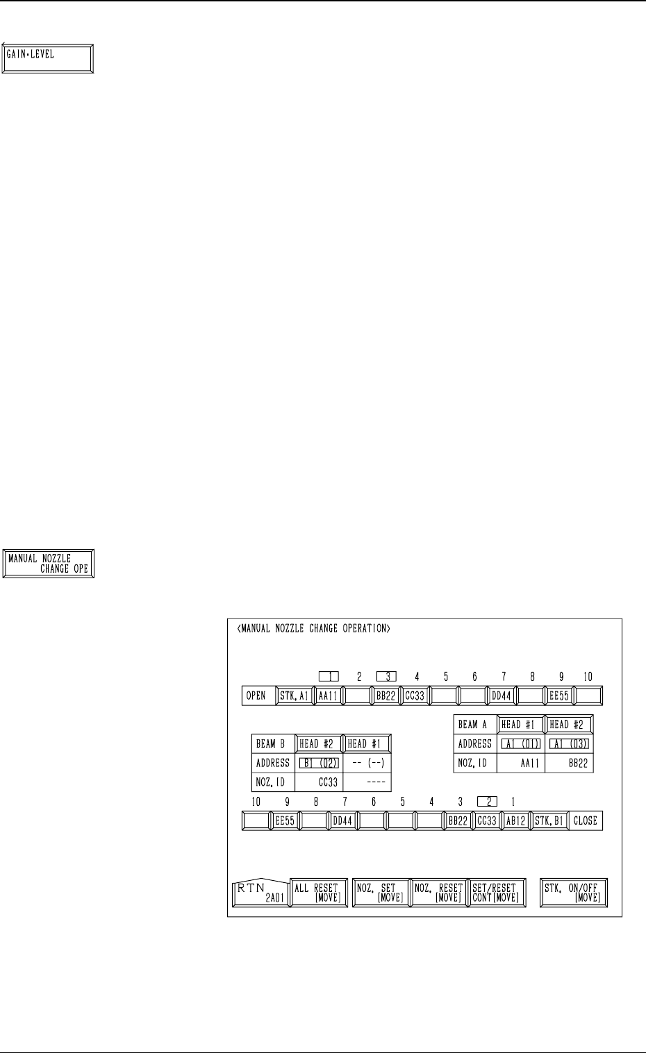
*11 [MANUAL NOZZLE CHANGE OPE] Key
When this key is pressed, the following display appears on
the screen.
Designate the head and the nozzle and attach the
“MF01”-, “MF02”-, or “MA06”-type nozzle to the head.
Refer to “9. Manual Nozzle Change Operation of Section
4 in Volume 1” for details.
3-57
6.2 COMP. RECOG. CAMERA MAG. (STEP-2) Display
Fig. 4C85
Fig. 4C83
Fig. 4C84