4OM-1011-002.pdf - 第116页
0305-001 Tg0860-PM-MM *1 [ALL BEAM] Key The machine performs the teaching operation of the head center of fset data for both heads on Beams A and B in the sequential order . When this key is selected and the [MOVE] butto…
0305-001 Tg0860-PM-MM
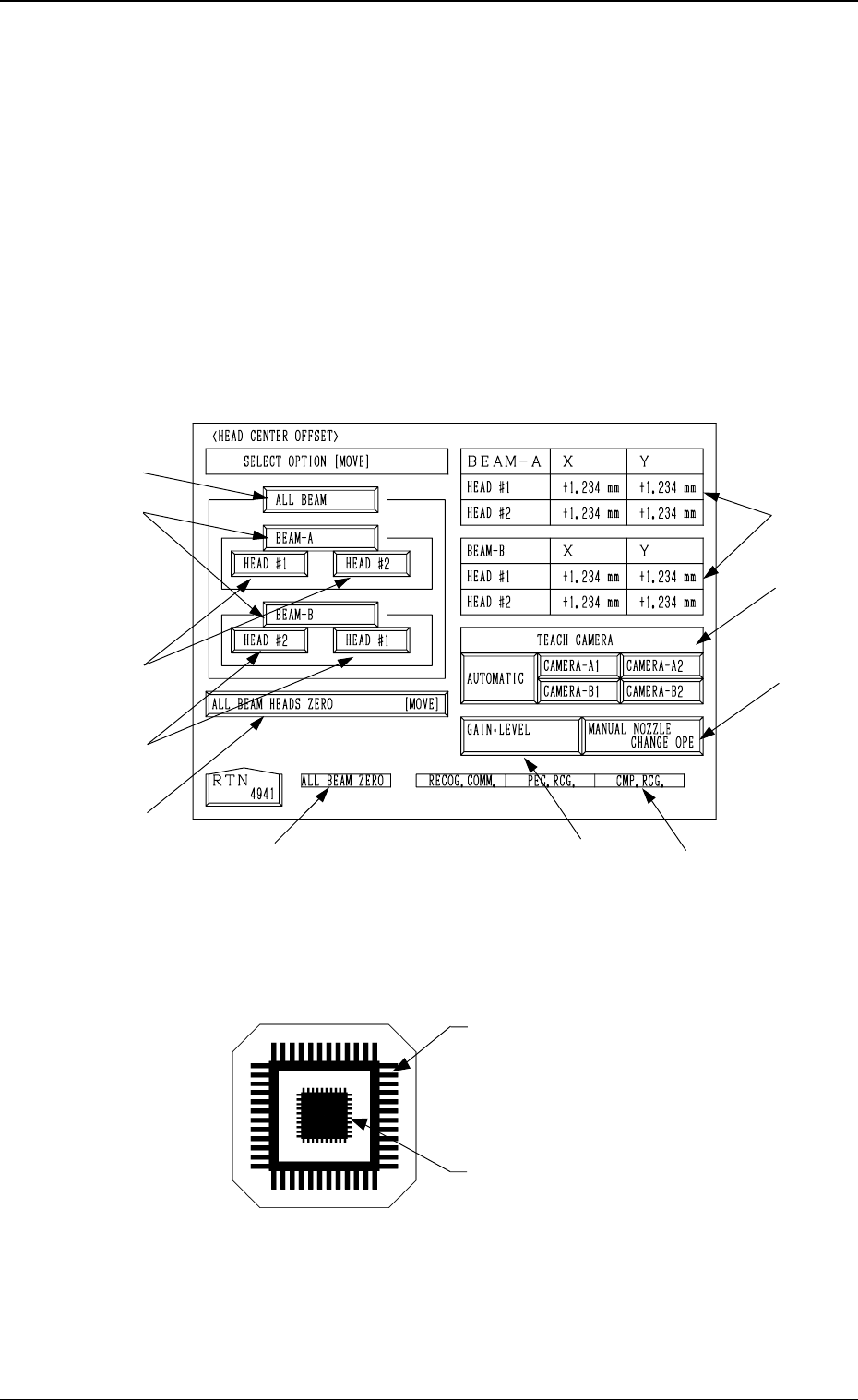
6.4 HEAD CENTER OFFSET Display
• This display allows teaching the head center offset data.
The offset values are calculated by recognizing the printed pattern on the jig
component (the teaching plate (component recognition offset jig)) picked
up by the nozzle separately at 0°, 90°, 180°, and 270°.
Note: Follow the teaching procedures in the specified order. Otherwise, some
trouble (such as inaccurate component placement, frequent mechani-
cal errors, etc.) will arise.
When the [HEAD CENTER OFFSET] key is pressed at the “TEACH OFF-
SET” display, the following display appears on the screen.
Teaching Plate (Component Recognition Offset Jig: JG-0085)
(Standard Accessory Part)
Note: Handle this fragile jig very carefully.
• Two types of patterns are printed through vapor deposition on the glass for
positional calculation.
*7
*9
*10
*2
*1
*3
*4
*3
*8
*6
*5
3-64
6.4 HEAD CENTER OFFSET Display
Fig. 4C102
Fig. 4C103
Pattern to be captured by the
component recognition camera
Pattern to be captured by the
P.E.C. recognition camera
0305-001 Tg0860-PM-MM
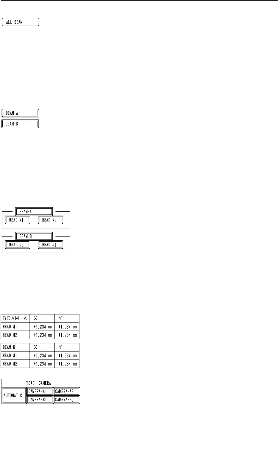
*1 [ALL BEAM] Key
The machine performs the teaching operation of the head
center offset data for both heads on Beams A and B in the
sequential order.
When this key is selected and the [MOVE] button is pressed,
the machine starts the teaching operation.
The keys with a red frame can not be selected because the
head skip setting has been performed for such keys.
Note: Before performing the teaching operations, zero
both beams.
*2 [BEAM-A] and [BEAM-B] Keys
The machine performs the teaching operations of the head
center offset data of both heads on Beam A or B.
When the [BEAM-A] or the [BEAM-B] key is selected
and the [MOVE] button is pressed, the machine performs
the teaching operation of the offset data related to the se-
lected beam.
The keys with a red frame can not be selected because the
head skip setting has been performed for such keys.
Note: Before performing the teaching operations, zero
both beams.
*3 [HEAD #1] and [HEAD #2] Keys in “BEAM-A” Group
Box and [HEAD #2] and [HEAD #1] Keys in “BEAM-B”
Group Box
The machine performs the teaching operation of the head
center offset data.
When one of the above-described keys is selected and the
[MOVE] button is pressed, the machine starts teaching the
offset data related to the selected head #.
The keys with a red frame can not be selected because the
head skip setting has been performed for such keys.
Note: Before performing the teaching operations, zero
both beams.
*4 Offset Data
Shown is the head center offset data of each head on Beams
A and B.
*5 TEACH CAMERA
A camera can be designated for teaching operations.
“AUTOMATIC”, “CAMERA-A1”, “CAMERA-A2”,
“CAMERA-B1”, or “CAMERA-B2” can be selected.
When “AUTOMATIC” is selected, a camera is automati-
cally selected for teaching operations.
When “CAMERA-A1”, “CAMERA-A2”, “CAMERA-
B1” or “CAMERA-B2” is designated, teaching operation
is performed in the designated camera.
3-65
6.4 HEAD CENTER OFFSET Display
Fig. 4C104
Fig. 4C105
Fig. 4C106
Fig. 4C107
Fig. 4C108
0305-001 Tg0860-PM-MM
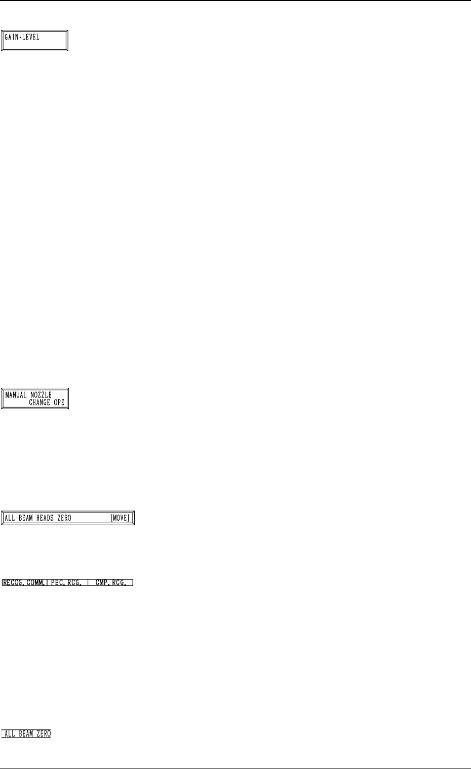
*6 [GAIN・LEVEL] Key
When this key is pressed, the “GAIN・LEVEL” display (Fig.
4C70) appears on the screen.
These parameters are used to set amplifications at which
the image signals of the image taken by the component rec-
ognition camera is converted into the picture information
representing brightness.
Parameters are set as the offset values for camera reference
gain and level.
Normal Fixed Value: ± 0
• When “ENABLE” is set in the “DESIGNATE” data box
at the “GAIN・LEVEL” display, be sure to set param-
eters in the “GAIN” and “LEVEL” data boxes.
The set parameters are used for P.E.C. recognition.
When “DISABLE” is set in the data box, the standard
parameters are set in the “GAIN” and “LEVEL” data
boxes.
• The lower the gain is, the bigger the contrast becomes.
• The lower the level is, the brighter the whole view be-
comes.
Note: Teaching operations are performed through com-
ponent recognition.
Incorrect gain and level parameters lead to the ad-
verse result of teaching operations, causing some
trouble.
*7 [MANUAL NOZZLE CHANGE OPE] Key
When this key is pressed, the “MANUAL NOZZLE
CHANGE OPERATION” display (Fig. 4C85) appears on
the screen.
Designate the head and the nozzle and attach either “MF01”-
, “MF02”- or “MA06”-type nozzle.
Refer to “9. Manual Nozzle Change Operation of Section
4 in Volume 1” for details.
*8 [ALL BEAM HEADS ZERO [MOVE]] Key
Both Beams A and B are zeroed.
When this key is selected and the [MOVE] button is pressed,
the zeroing operation starts.
*9 RECOG. COMM.
When “DISABLE” is set in the “P.E.C.” and “COMPO-
NENT RECOGNITION” data boxes at the “TEST MODE”
display, the background color of “P.E.C. RECOG.” and
“COMP. RECOG.” becomes light red. (No background
color in normal cases).
Note: In this case, the recognition processing is not made
even if the teaching operations are performed.
Therefore, the results of various teaching opera-
tions are not reflected on the offset data.
*10 ALL BEAM ZERO
When all beams are zeroed completely, the background
color turns green. Otherwise, the background has no color.
3-66
6.4 HEAD CENTER OFFSET Display
Fig. 4C109
Fig. 4C110
Fig. 4C111
Fig. 4C112
Fig. 4C113