4OM-1011-002.pdf - 第127页
0305-001 Tg0860-PM-MM 6.7 HEAD ROT A TION OFFSET Display • This display allows teaching the of fset data to correct the angular deviation between the nozzle clamp lever and the P .C.B. positioning reference with the moto…
0305-001 Tg0860-PM-MM
Operation Procedure
• Required Items
Nozzle: 4 pieces of “MF01”, “MF02” or “MA06”
Jig Component: Teaching Plate (Component Recognition Offset Jig)
(Standard Accessory Part)
(1) Set either “MF01”-, “MF02”- or “MA06”-type nozzle in the nozzle
stocker.
(2) Attach the jig component (the teaching plate (component recognition
offset jig)) to the position where the teaching plate is attached.
Note: The printed side of the component recognition offset jig should
face downward.
(3) Check the followings.
• Check that the machine is powered.
• Check that the supply cover is completely closed.
(4) Attach either “MF01”-, “MF02”- or “MA06”-type nozzle to the ob-
jective placement head for teaching at the “MANUAL NOZZLE
CHANGE OPERATION” display.
(5) Select the [ALL BEAM HEADS ZERO [MOVE]] key and press the
[MOVE] button to zero all beam heads.
Confirm that the background color of “ALL BEAM ZERO” has turned
green.
(6) To specify the gain and level, use the “GAIN・LEVEL” display.
Note: In normal cases, set “DISABLE” in the “DESIGNATE” data
box.
(7) Select the item to be taught and press the [MOVE] button.
The machine starts the teaching operations.
The following series of teaching operations are performed automati-
cally.
The nozzle picks up the teaching plate from the place where the teach-
ing plate is attached.
↓
The placement head moves to the component recognition camera po-
sition.
↓
The jig component is recognized with the component recognition cam-
era. The component posture (4 directions: 0°, 90°, 180°, and 270°) is
checked and the deviations from the head rotational and camera cen-
ters are extracted during the recognition.
↓
The teaching plate is returned to the original place (the place where it
was attached).
Ref.: The checker marks at the component recognition camera sec-
tion are also recognized.
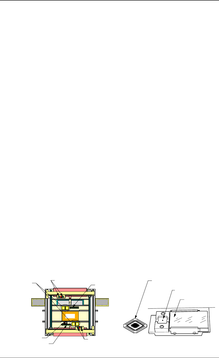
Overall Top View
Teaching Plate Section
Component Rec-
ognition Camera
Nozzle Stocker
Placement Head
Nozzle Stocker
Placement Head
Beam A Side
Teaching Plate
(Component Recognition Offset Jig)
Position of Teaching Plate
Back Light Stage
Beam B Side
Magnified View of Teaching Plate Section
3-75
6.6 HEAD OFFSET (GET BOTH IMAGE) Display
Fig. 4C138
0305-001 Tg0860-PM-MM
6.7 HEAD ROTATION OFFSET Display
• This display allows teaching the offset data to correct the angular deviation
between the nozzle clamp lever and the P.C.B. positioning reference with
the motor (for head rotational shaft) located at its origin.
Calculate the bending of the nozzle clamping lever with the component cam-
era, regarding the special jig nozzle (option) as a component.
• Teaching operations are performed through two steps (coarse and accurate
angle teaching steps). The coarse step is taken to calculate an approximate
angular deviation and the accurate one to calculate an accurate angular de-
viation.
Notes: (a) A special jig nozzle (option) is required.
The parameters are factory-set at shipment. Normally, it is not
necessary to teach these parameters.
(b) Various parameter settings and some preparation are required be-
fore teaching operations.
When a teaching operation is performed under the condition that
the parameters are not set correctly and the required preparation
is not made, some trouble will arise.
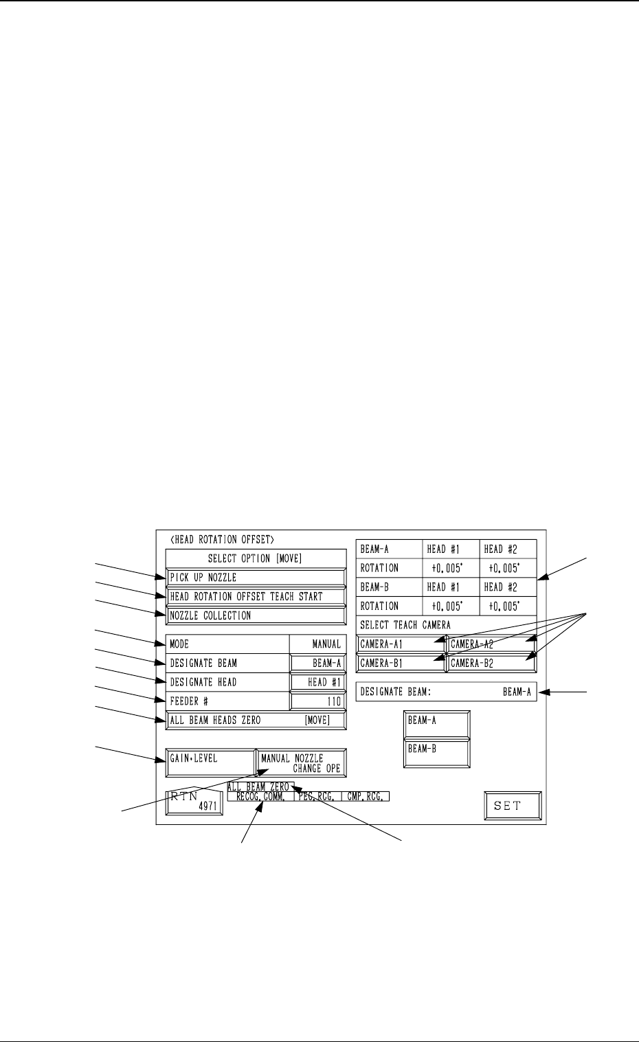
When the [HEAD ROTATION OFFSET] key is pressed at the “TEACH OFF-
SET” display, the following display appears on the screen.
*11
*12
*13
*1
*2
*3
*4
*5
*6
*7
*8
*9
*10
*14
*15
3-76
6.7 HEAD ROTATION OFFSET Display
Fig. 4C139
0305-001 Tg0860-PM-MM
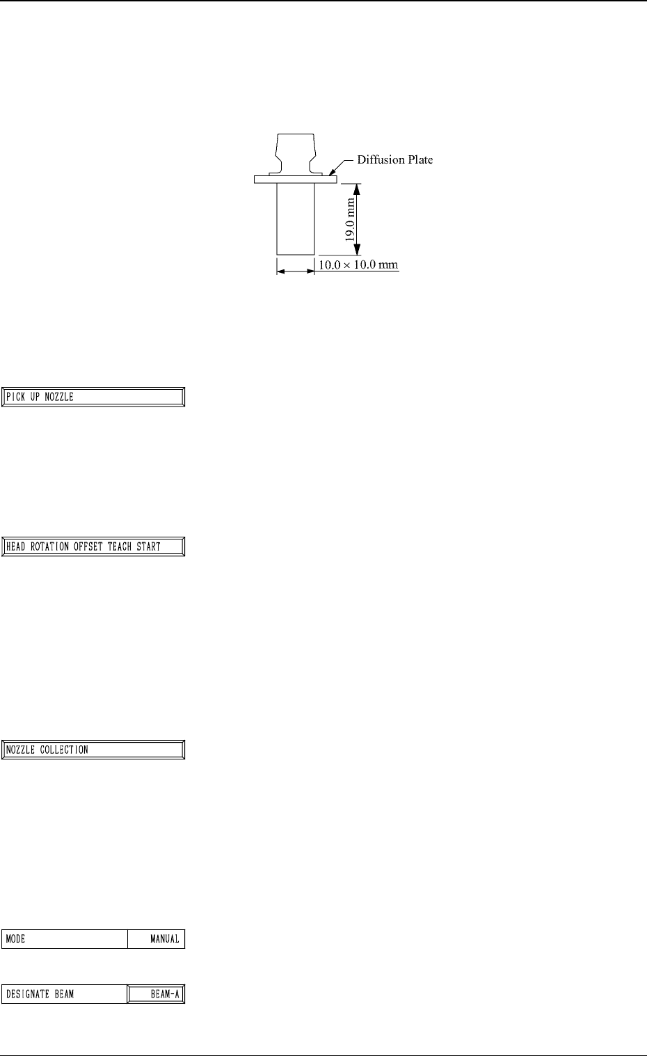
Special Jig Nozzle (Option)
Note: Consult our sales personnel for the detailed informa-
tion on how to use the special jig nozzle.
Name: Head Angle Setting Jig Nozzle (JG01)
Model Name: JG-0094
*1 [PICK UP NOZZLE] Key
The head (the head designated by setting parameters in the
“DESIGNATE BEAM” and “DESIGNATE HEAD” data
boxes) moves to the feeder # (the feeder # designated by
setting a parameter in the “FEEDER #” data box).
When this key is selected and the [MOVE] button is pressed,
the head moves to the designated feeder #.
*2 [HEAD ROTATION OFFSET TEACH START] Key
The machine performs the teaching operation of the rota-
tional angle offset data of the head selected by setting pa-
rameters in the “DESIGNATE BEAM” and “DESIGNATE
HEAD” data boxes.
When this key is selected and the [MOVE] button is pressed,
the machine starts the teaching operation.
Note: Before performing the teaching operations, be sure
to pick up the special jig nozzle and zero both
beams.
*3 [NOZZLE COLLECTION] Key
The machine works to collect the attached special jig nozzle.
When this key is selected and the [MOVE] button is pressed,
the head moves to the feeder # selected by setting a param-
eter in the “FEEDER #” data box. The special jig nozzle
must be collected by hand.
Note: After the teaching operation is completed, be sure
to collect the nozzle and detach the special jig
nozzle from the head.
*4 MODE
Only “MANUAL” is available.
*5 DESIGNATE BEAM
This allows designating the beam where the special jig
nozzle is picked up.
Set either “BEAM-A” or “BEAM-B” in the data box.
3-77
6.7 HEAD ROTATION OFFSET Display
Fig. 4C140
Fig. 4C141
Fig. 4C142
Fig. 4C143
Fig. 4C144
Fig. 4C145