4OM-1011-002.pdf - 第136页
0305-001 Tg0860-PM-MM *4 [FEEDER BASE #1 (1 19)], [FEEDER BASE #2 (121)], [FEEDER BASE #3 (219)], and [FEEDER BASE #4 (221)] Keys Install the master feeder in the specified feeder slot No. on the feeder base whose offset…
0305-001 Tg0860-PM-MM
6.8.1 Feeder Base Offset
• Attach the master jig (standard accessory part) to the specified feeder No.
position (119, 121, 221, and 219) and perform the teaching operation for the
offset data of the master jig through manual alignment operation.
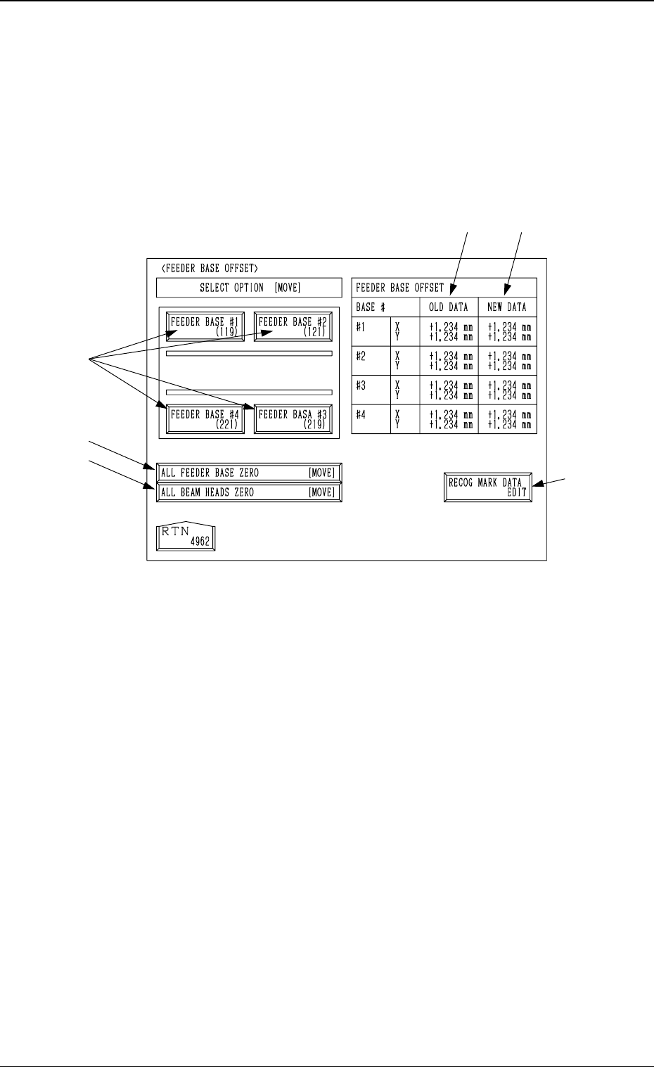
When the [FEEDER BASE OFFSET] key is pressed at the “UNIT MANUAL
ALIGNMENT TEACH” display, the following display appears on the screen.
.
*1 [RECOG MARK DATA EDIT] Key
When this key is pressed, the “RECOG. MARK DATA EDIT” display (Fig.
4C168) appears on the screen, enabling the designation of a template shape
to appear on the recognition monitor.
The template shape can be specified for manual alignment with the align-
ment point.
Refer to “6.8.8 Editing of Recognition Mark Data” for details.
*2 [ALL FEEDER BASE ZERO] Key
All feeder bases are zeroed.
When this key is selected and the [MOVE] button is pressed, the zeroing
operation starts.
*3 [ALL BEAM HEADS ZERO] Key
Both Beams A and B are zeroed.
When this key is selected and the [MOVE] button is pressed, the zeroing
operation starts.
*4
*2
*3
*5
*1
*6
3-84
6.8 UNIT MANUAL ALIGNMENT TEACH Display
Fig. 4C158

0305-001 Tg0860-PM-MM
*4 [FEEDER BASE #1 (119)], [FEEDER BASE #2 (121)],
[FEEDER BASE #3 (219)], and [FEEDER BASE #4 (221)] Keys
Install the master feeder in the specified feeder slot No. on the feeder base
whose offset data must be taught.
Select the key which corresponds to the feeder base whose offset data
must be taught and press the [MOVE] button. The P.E.C. recognition cam-
era moves to the position where the master feeder is located.
The teaching point of the master feeder appears on the recognition monitor.
Perform the manual alignment, using the track ball.
Refer to “6.8.9 Teaching Operation with Trackball” for details.
*5 OLD DATA
Displayed are the values (the parameters related to the indicated base #)
before the feeder base offset is taught.
*6 NEW DATA
Displayed are the values (the parameters related to the indicated base #)
after the feeder base offset is taught.
Before the teaching operation is performed, the same values as *5 are dis-
played.
3-85
6.8 UNIT MANUAL ALIGNMENT TEACH Display
0305-001 Tg0860-PM-MM
6.8.2 Feeder (A) Offset
• When the master feeder is installed in each feeder slot No. and the manual
alignment operation is performed, the offset values for the master feeder are
taught.
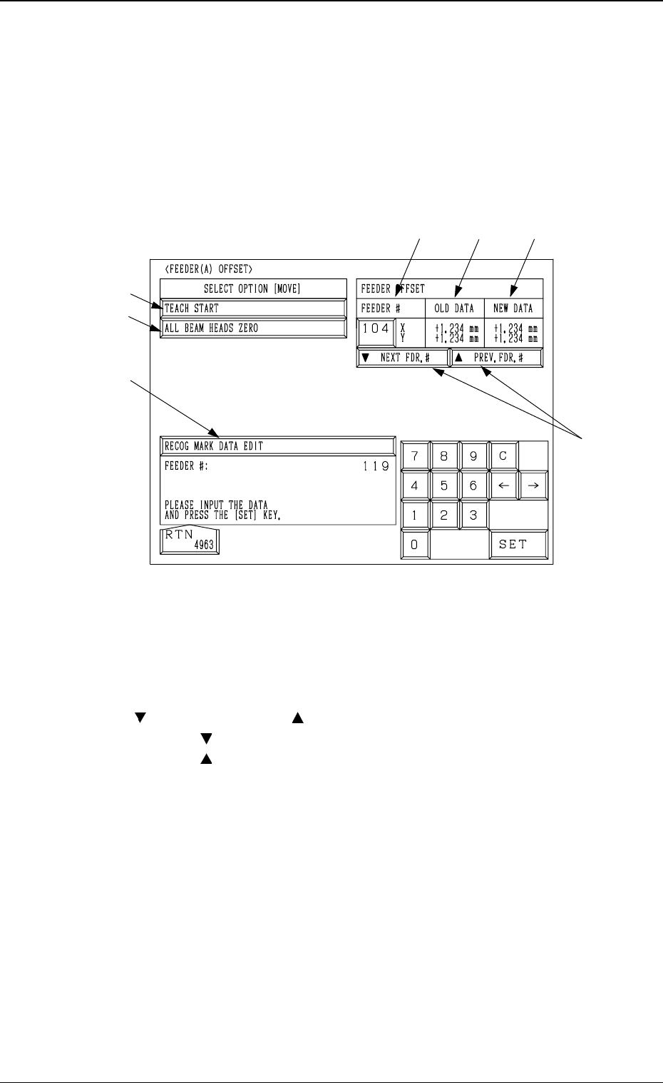
When the [FEEDER (A) OFFSET] key is pressed at the “UNIT MANUAL
ALIGNMENT TEACH” display, the following display appears on the screen.
*1 FEEDER #
A feeder slot No. can be set for manual alignment and teaching operations.
Install the master feeder in the specified slot No.
*2 [ NEXT FDR. #] and [ PREV. FDR. #] Keys
When the [ NEXT FDR. #] key is pressed, the feeder # increases by 1.
When the [ PREV. FDR. #] key is pressed, the feeder # decreases by 1.
*3 [RECOG MARK DATA EDIT] Key
When this key is pressed, the “RECOG. MARK DATA EDIT” display (Fig.
4C168) appears on the screen, enabling the designation of a template shape
to appear on the recognition monitor.
The template shape can be specified for manual alignment with the align-
ment point.
Refer to “6.8.8 Editing of Recognition Mark Data” for details.
*4 [ALL BEAM HEADS ZERO] Key
Both Beams A and B are zeroed.
When this key is selected and the [MOVE] button is pressed, the zeroing
operation starts.
*1
*2
*5
*4
*3
*6
*7
3-86
6.8 UNIT MANUAL ALIGNMENT TEACH Display
Fig. 4C159