4OM-1011-002.pdf - 第147页
0305-001 Tg0860-PM-MM 6.8.6 T eaching Plate Offset • The offset values for the teaching plate position can be taught through manual alignment operation. When the [TEACHING PLA TE OFFSET] key is pressed at the “UNIT MANUA…
0305-001 Tg0860-PM-MM
Special Jig (Option)
Note: Consult our sales personnel for the detailed information on how to use
the special jig.
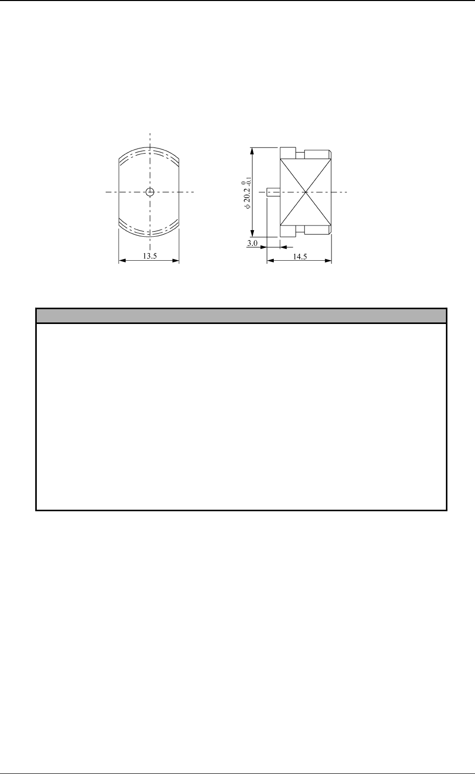
Name : Nozzle Stocker Positioning Jig
Model Name: JG-0101
Dimensions : Approx. φ 20.2 (diameter) × 14.5 mm (thickness)
Reference
1. How to input the offset data accurately
(1) Perform the teaching operation at several places such as nozzle stocker addresses 1 and 10.
Jot down the values obtained through teaching operations.
(2) Enter the mean values obtained through teaching operation as nozzle stocker offset data.
Refer to “7. NOZZLE STOCKER OFFSET Display of Section 5 in Volume 2” for details on
how to enter the offset data.
2. How to perform the simplified teaching operation, using a nozzle (not a jig)
Teach the nozzle center position.
Notes: (a) It is recommended that the steps in “1. How to input the offset data accurately”
should be taken because this method will make it difficult to manually align the
nozzle center position accurately.
(b) Be sure to set nozzle through head movement operation.
If a nozzle is set by hand, it may not be stored correctly in place.
In this case, the mean values of the offset data taught at several stocker addresses must be
entered similarly to the step described in “1. How to input the offset data accurately”.
Fig. 4C165
3-95
6.8 UNIT MANUAL ALIGNMENT TEACH Display
0305-001 Tg0860-PM-MM
6.8.6 Teaching Plate Offset
• The offset values for the teaching plate position can be taught through manual
alignment operation.
When the [TEACHING PLATE OFFSET] key is pressed at the “UNIT
MANUAL ALIGNMENT TEACH” display, the following display appears on
the screen.
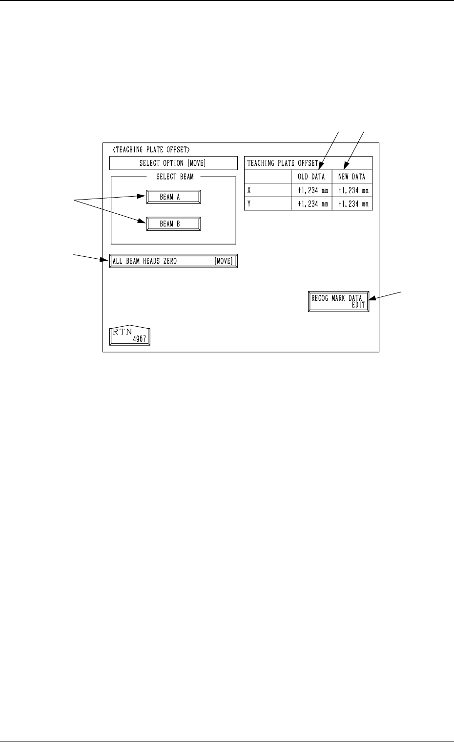
*1 [RECOG MARK DATA EDIT] Key
When this key is pressed, the “RECOG. MARK DATA EDIT” display (Fig.
4C168) appears on the screen, enabling the designation of a template shape
to appear on the recognition monitor.
The template shape can be specified for manual alignment with the align-
ment point.
Refer to “6.8.8 Editing of Recognition Mark Data” for details.
*2 [ALL BEAM HEADS ZERO [MOVE]] Key
Both Beams A and B are zeroed.
When this key is selected and the [MOVE] button is pressed, the zeroing
operation starts.
*3 [BEAM A] and [BEAM B] Keys
When either one of the [BEAM A] and [BEAM B] keys is selected and the
[MOVE] button is pressed, the P.E.C. camera moves to the specified point
on the teaching plate.
The teaching point (the center hole located at the teaching plate position)
appears on the recognition monitor. Perform the manual alignment using the
trackball.
Refer to “6.8.9 Teaching Operation with Trackball” for details.
*4 TEACHING PLATE OFFSET OLD DATA
Displayed are the values before the teaching plate offset data is taught.
*5 TEACHING PLATE OFFSET NEW DATA
Displayed are the values after the teaching plate offset data is taught.
Before the teaching operation is performed, the same values as *4 are dis-
played.
*3
*1
*5
*2
*4
3-96
6.8 UNIT MANUAL ALIGNMENT TEACH Display
Fig. 4C166
0305-001 Tg0860-PM-MM
6.8.7 Traverse Offset (Option)
• The offset data for the traverse pullout position can be taught through manual
alignment operation.
Note: The traverse shaft must be pulled out in advance by the multi-layer tray
feeder (option) in the “LOCAL” mode.
Refer to the instruction manual of the multi-layer tray feeders for de-
tails.
When the [TRAVERSE OFFSET] key is pressed at the “UNIT MANUAL
ALIGNMENT TEACH” display, the following display appears on the screen.
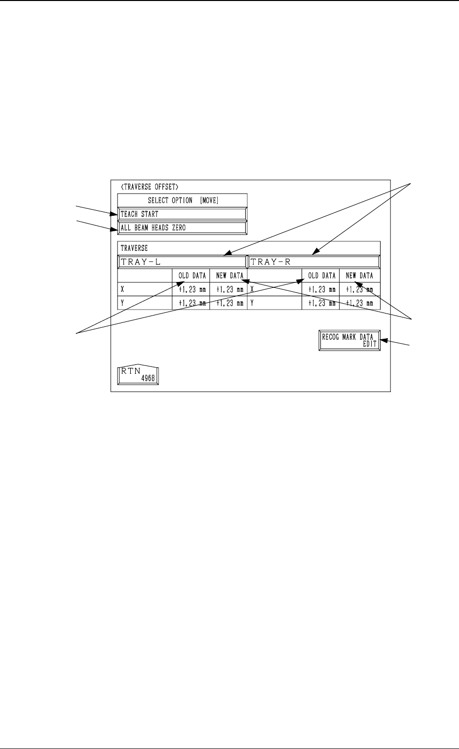
*1 [TRAY-L] and [TRAY-R] Keys
When one of these keys is pressed, the traverse shaft (the traverse shaft for
Tray L or Tray R) corresponding to the selected key is selected.
*2 [RECOG MARK DATA EDIT] Key
When this key is pressed, the “RECOG. MARK DATA EDIT” display (Fig.
4C168) appears on the screen, enabling the designation of a template shape
to appear on the recognition monitor.
The template shape can be specified for manual alignment with the align-
ment point.
Refer to “6.8.8 Editing of Recognition Mark Data” for details.
*3 [ALL BEAM HEADS ZERO] Key
Both Beams A and B are zeroed.
When this key is selected and the [MOVE] button is pressed, the zeroing
operation starts.
*4 [TEACH START] Key
When this key is selected and the [MOVE] button is pressed, the P.E.C.
recognition camera moves to the specified point of the traverse unit.
The teaching point appears on the recognition monitor. Perform the manual
alignment using the track ball.
Refer to “6.8.9 Teaching Operation with Track Ball” for details.
*5 TRAVERSE OLD DATA
Displayed are the values before the traverse pullout position is taught.
*6 TRAVERSE NEW DATA
Displayed are the values after the traverse pullout position is taught.
Before the teaching operation is performed, the same values as *5 are dis-
played.
*3
*4
*1
*6
*5
*2
3-97
6.8 UNIT MANUAL ALIGNMENT TEACH Display
Fig. 4C167