4OM-1011-002.pdf - 第148页
0305-001 Tg0860-PM-MM 6.8.7 T raverse Offset (Option) • The offset data for the traverse pullout position can be taught through manual alignment operation. Note: The traverse shaft must be pulled out in advance by the mu…
0305-001 Tg0860-PM-MM
6.8.6 Teaching Plate Offset
• The offset values for the teaching plate position can be taught through manual
alignment operation.
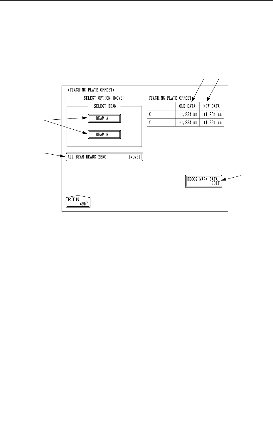
When the [TEACHING PLATE OFFSET] key is pressed at the “UNIT
MANUAL ALIGNMENT TEACH” display, the following display appears on
the screen.
*1 [RECOG MARK DATA EDIT] Key
When this key is pressed, the “RECOG. MARK DATA EDIT” display (Fig.
4C168) appears on the screen, enabling the designation of a template shape
to appear on the recognition monitor.
The template shape can be specified for manual alignment with the align-
ment point.
Refer to “6.8.8 Editing of Recognition Mark Data” for details.
*2 [ALL BEAM HEADS ZERO [MOVE]] Key
Both Beams A and B are zeroed.
When this key is selected and the [MOVE] button is pressed, the zeroing
operation starts.
*3 [BEAM A] and [BEAM B] Keys
When either one of the [BEAM A] and [BEAM B] keys is selected and the
[MOVE] button is pressed, the P.E.C. camera moves to the specified point
on the teaching plate.
The teaching point (the center hole located at the teaching plate position)
appears on the recognition monitor. Perform the manual alignment using the
trackball.
Refer to “6.8.9 Teaching Operation with Trackball” for details.
*4 TEACHING PLATE OFFSET OLD DATA
Displayed are the values before the teaching plate offset data is taught.
*5 TEACHING PLATE OFFSET NEW DATA
Displayed are the values after the teaching plate offset data is taught.
Before the teaching operation is performed, the same values as *4 are dis-
played.
*3
*1
*5
*2
*4
3-96
6.8 UNIT MANUAL ALIGNMENT TEACH Display
Fig. 4C166
0305-001 Tg0860-PM-MM
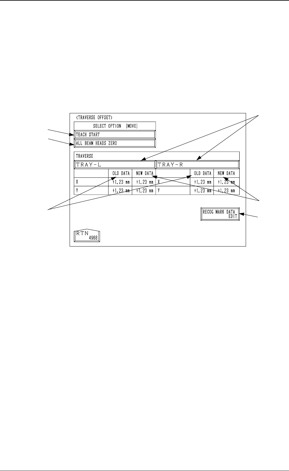
6.8.7 Traverse Offset (Option)
• The offset data for the traverse pullout position can be taught through manual
alignment operation.
Note: The traverse shaft must be pulled out in advance by the multi-layer tray
feeder (option) in the “LOCAL” mode.
Refer to the instruction manual of the multi-layer tray feeders for de-
tails.
When the [TRAVERSE OFFSET] key is pressed at the “UNIT MANUAL
ALIGNMENT TEACH” display, the following display appears on the screen.
*1 [TRAY-L] and [TRAY-R] Keys
When one of these keys is pressed, the traverse shaft (the traverse shaft for
Tray L or Tray R) corresponding to the selected key is selected.
*2 [RECOG MARK DATA EDIT] Key
When this key is pressed, the “RECOG. MARK DATA EDIT” display (Fig.
4C168) appears on the screen, enabling the designation of a template shape
to appear on the recognition monitor.
The template shape can be specified for manual alignment with the align-
ment point.
Refer to “6.8.8 Editing of Recognition Mark Data” for details.
*3 [ALL BEAM HEADS ZERO] Key
Both Beams A and B are zeroed.
When this key is selected and the [MOVE] button is pressed, the zeroing
operation starts.
*4 [TEACH START] Key
When this key is selected and the [MOVE] button is pressed, the P.E.C.
recognition camera moves to the specified point of the traverse unit.
The teaching point appears on the recognition monitor. Perform the manual
alignment using the track ball.
Refer to “6.8.9 Teaching Operation with Track Ball” for details.
*5 TRAVERSE OLD DATA
Displayed are the values before the traverse pullout position is taught.
*6 TRAVERSE NEW DATA
Displayed are the values after the traverse pullout position is taught.
Before the teaching operation is performed, the same values as *5 are dis-
played.
*3
*4
*1
*6
*5
*2
3-97
6.8 UNIT MANUAL ALIGNMENT TEACH Display
Fig. 4C167
0305-001 Tg0860-PM-MM
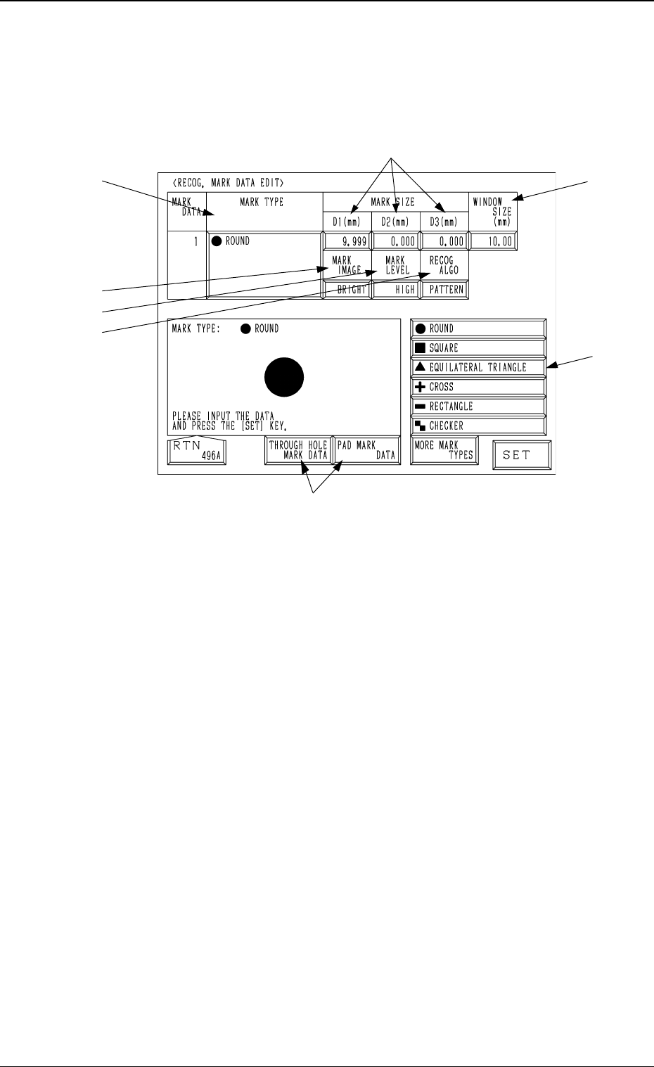
6.8.8 Editing of Recognition Mark Data
When the [RECOG MARK DATA EDIT] key is pressed at the manual align-
ment and teaching display for each device, the following display appears on the
screen.
*1 MARK TYPE
Specify the shape of the template.
Select the data box under the label “MARK TYPE” and press one of the
keys *8.
*2 MARK SIZE
Enter the dimensions of the template in the “D1(mm)”, “D2(mm)”, and
“D3(mm)” data boxes.
*3 WINDOW SIZE
Set the area to be recognized.
*4 MARK IMAGE
Set the brightness of the mark in the data box.
Set “BRIGHT” in the data box.
*5 MARK LEVEL
The set parameter is not used here.
*6 RECOG ALGO
The set parameter is not used here.
*7 [P.E.C. MARK DATA], [THROUGH HOLE MARK DATA] and [PAD
MARK DATA] Keys
Mark type group can be selected from [P.E.C. MARK DATA], [THROUGH
HOLE MARK DATA] or [PAD MARK DATA].
The mark types in *8 belong to the selected data and can be selected.
*8 Mark Type Keys
Select the data box under the label “MARK TYPE” or enter a parameter
and then press the [SET] key.
Each data item is the same as the P.E.C. mark data.
Refer to “2.3.4 P.E.C. MARK DATA EDIT Display of Section 2 in Volume
2” for details.
*7
3-98
6.8 UNIT MANUAL ALIGNMENT TEACH Display
Fig. 4C168
*4
*1
*8
*3
*2
*5
*6