4OM-1011-002.pdf - 第150页
0305-001 Tg0860-PM-MM 6.8.9 T eaching Operation with T rackball (1) When the manual alignment and teaching operations are implemented, the captured image and the template for teaching appear on the recognition monitor . …
0305-001 Tg0860-PM-MM
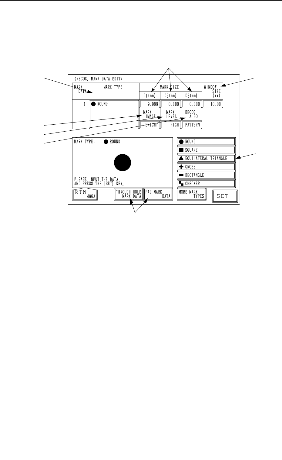
6.8.8 Editing of Recognition Mark Data
When the [RECOG MARK DATA EDIT] key is pressed at the manual align-
ment and teaching display for each device, the following display appears on the
screen.
*1 MARK TYPE
Specify the shape of the template.
Select the data box under the label “MARK TYPE” and press one of the
keys *8.
*2 MARK SIZE
Enter the dimensions of the template in the “D1(mm)”, “D2(mm)”, and
“D3(mm)” data boxes.
*3 WINDOW SIZE
Set the area to be recognized.
*4 MARK IMAGE
Set the brightness of the mark in the data box.
Set “BRIGHT” in the data box.
*5 MARK LEVEL
The set parameter is not used here.
*6 RECOG ALGO
The set parameter is not used here.
*7 [P.E.C. MARK DATA], [THROUGH HOLE MARK DATA] and [PAD
MARK DATA] Keys
Mark type group can be selected from [P.E.C. MARK DATA], [THROUGH
HOLE MARK DATA] or [PAD MARK DATA].
The mark types in *8 belong to the selected data and can be selected.
*8 Mark Type Keys
Select the data box under the label “MARK TYPE” or enter a parameter
and then press the [SET] key.
Each data item is the same as the P.E.C. mark data.
Refer to “2.3.4 P.E.C. MARK DATA EDIT Display of Section 2 in Volume
2” for details.
*7
3-98
6.8 UNIT MANUAL ALIGNMENT TEACH Display
Fig. 4C168
*4
*1
*8
*3
*2
*5
*6
0305-001 Tg0860-PM-MM
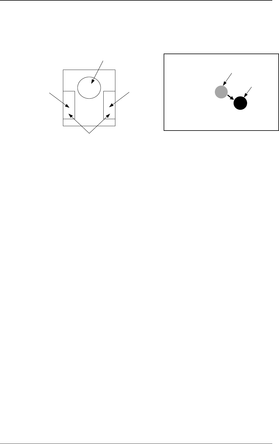
6.8.9 Teaching Operation with Trackball
(1) When the manual alignment and teaching operations are implemented, the
captured image and the template for teaching appear on the recognition
monitor.
(2) Use the trackball to move the template and align it with the teaching point.
(3) When you press the right button of the trackball, the image size extends.
Pressing the left button reduces the image size. Adjust the size so that the
template and the teaching point overlap each other.
(4) Press the left and right buttons of the trackball simultaneously. The posi-
tion is determined.
3-99
6.8 UNIT MANUAL ALIGNMENT TEACH Display
Fig. 4C170Fig. 4C169
Right Button
Function: Image
Extension
Left Button
Function: Image Reduction
Pressing the left and right buttons simultaneously:
Determination of Position
Template
Image
Image on Recognition Monitor
Trackball
Function: Template Movement
0305-001 Tg0860-PM-MM
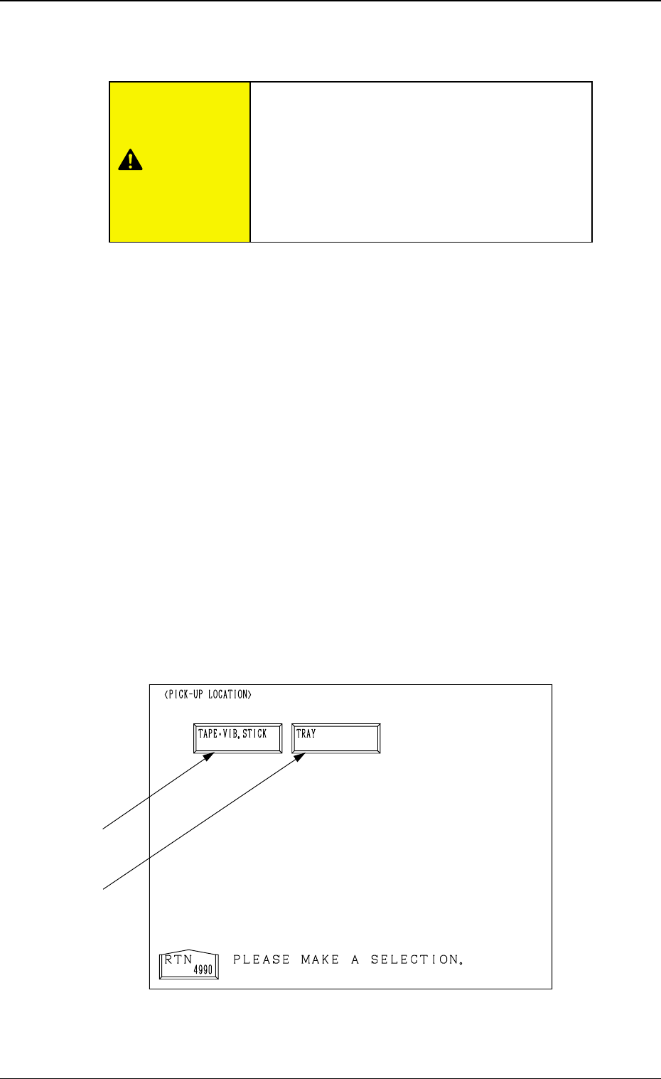
6.9 PICK-UP LOCATION Display
• The pick-up position of the component at each feeder is taught through manual
alignment operation.
The objective feeders for teaching are those whose pick-up position is regis-
tered in the component data of the current pattern program.
The pick-up rate may be improved after the teaching of the pick-up position
is performed when the pick-up rate is low.
• When the center of the cross lines does not match the center of the compo-
nent on the recognition monitor during teaching operation, perform the teaching
operation of the feeder (B) offset data.
• When a component has a groove, a protrusion, etc., and cannot be picked up
at the center without any hindrance, it is possible to perform the teaching
operation on the designation of eccentric pick-up (Chuck Location Adjust-
ment X and Y in Component Library Data).
When the [PICK-UP LOCATION] key is pressed at the “TEACH OFFSET”
display, the following display appears on the screen.
This display can also be opened from the “AUTO OPN. SUB-MENU”
display. (Hierarchical Sequence: “AUTO OPN MODE <PLACEMENT>”
Display → “AUTO OPN. SUB-MENU” Display)
Note: This key can be selected only when the machine is in the “STOP”
mode.
3-100
6.9 PICK-UP LOCATION Display
Fig. 4C171
*2
*1
CAUTION
Only a well-trained personnel shall perform
teaching operations.
The component library data and the pattern pro-
gram may be modified additionally for the teach-
ing.
If the teaching operation is not performed cor-
rectly, the pick-up rate may deteriorate.