4OM-1011-002.pdf - 第155页
0305-001 Tg0860-PM-MM *3 “SELECT OPTION” [TEACH PICK-UP POS. [COMP . CENTER POS.]] Key When this key is pressed, the display (Fig. 4C172) ap- pears on the screen. T o teach the center position of the component, use this …
0305-001 Tg0860-PM-MM
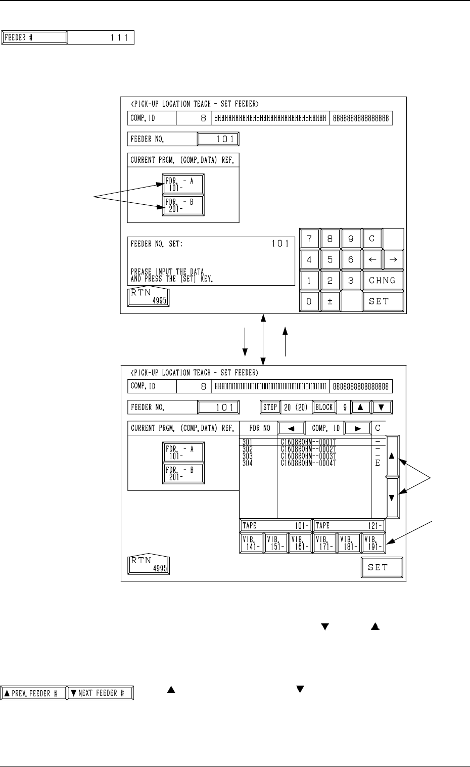
*1 [FEEDER #] Key
When this key is pressed, the “PICK-UP LOCATION
TEACH - SET FEEDER” display (Fig. 4C175) appears on
the screen, enabling the setting of the feeder No. whose
pick-up location must be taught.
Procedure for Feeder Selection
(1) Select one of the keys A to specify the feeder base.
(2) Select the feeder No., using the [ ] or the [ ] key B.
To teach the data related to the vibratory stick feeder,
select one of the keys C to specify the feeder carriage.
(3) Press the [SET] key.
*2 [ PREV. FEEDER #] and [ NEXT FEEDER #] Keys
The feeder Nos. registered in the component data of the
current program are scrolled up or down.
This function automatically skips the feeder Nos. which are
not specified in the current program or the feeder Nos. for
which no components are set in the component data.
[FDR. -A 101- ]
B
C
[101]
Fig. 4C175
A
Fig. 4C176
3-103
6.10 PICK-UP LOCATION (TAPE·VIB. STICK) Display
Fig. 4C174
Fig. 4C177
0305-001 Tg0860-PM-MM
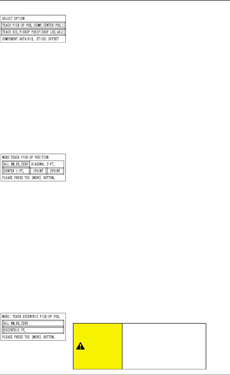
*3 “SELECT OPTION”
[TEACH PICK-UP POS. [COMP. CENTER POS.]] Key
When this key is pressed, the display (Fig. 4C172) ap-
pears on the screen.
To teach the center position of the component, use this
function for the “FEEDER (B) OFFSET” teaching.
[TEACH ECC. PICKUP POS [PICKUP LOC. ADJ]] Key
When this key is pressed, the display (Fig. 4C173) ap-
pears on the screen.
When a component has a groove, a protrusion, etc., and
cannot be picked up at the center without any hindrance,
use this function for the “PICK-UP LOCATION AD-
JUSTMENT X, Y” teaching.
[COMPONENT DATA (VIB. STICK) OFFSET] Key
When this key is pressed, the display (Fig. 4C195) ap-
pears on the screen.
Use this function to teach “OFFSET X, Y”.
This key can be selected only when the feeder No. se-
lected in *1 is allocated to a vibratory stick feeder.
*4 “MODE: TEACH PICK-UP POSITION”
This is used to additionally modify “FEEDER (B) OFFSET
X, Y”.
[ALL BM. HD. ZERO] Key
Both Beams A and B are zeroed.
When this key is selected and the [MOVE] button is
pressed, the zeroing operation starts.
[CENTER 1-PT.] Key
When this key is selected and the [MOVE] button is
pressed, the P.E.C. recognition camera moves to the com-
ponent center position (Position of “Design Position +
Feeder (A) Offset + Feeder (B) Offset”) of the perti-
nent feeder, making it possible to capture the image.
Under this condition, shift to the trackball operation and
perform the manual alignment operation.
“DIAGONAL 2-PT.” [1POINT] and [2POINT] Keys
These keys are used to align the component with two
diagonally-located points.
Use this function when the maximum outside dimensions
of the component exceed “10 × 10 mm” (when the whole
image of the component cannot be captured on the rec-
ognition monitor).
*5 “MODE: TEACH ECCENTRIC PICK-UP POS.”
6.10 PICK-UP LOCATION (TAPE·VIB. STICK) Display
3-104
Fig. 4C178
Fig. 4C179
Fig. 4C180
“PICK-UP LOCATION ADJUST-
MENT X, Y” in the component li-
brary data is modified additionally.
Incorrect teaching operation will
cause the pick-up rate to deterio-
rate.
CAUTION
0305-001 Tg0860-PM-MM
[ALL BM. HD. ZERO] Key
Both Beams A and B are zeroed.
When this key is selected and the [MOVE] button is
pressed, the zeroing operation starts.
[ECCENTRIC PT.] Key
When this key is selected and the [MOVE] button is
pressed, the P.E.C. recognition camera moves to the des-
ignated pick-up location correction position based on the
component center position (Position of “Design Position
+ Feeder (A) Offset + Feeder (B) Offset”) of the perti-
nent feeder, making it possible to capture the image.
Under this condition, shift to the trackball operation and
perform the manual alignment operation.
Note: It is necessary to correctly teach the component
center position before the eccentric position is
adjusted.
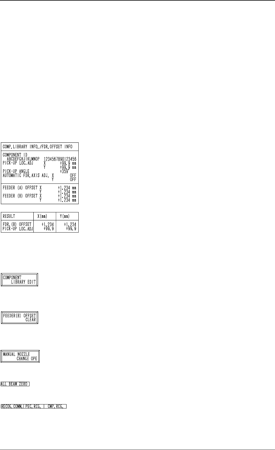
*6 “COMP. LIBRARY INFO./FDR. OFFSET INFO”
Displayed are the component library data and the feeder
offset of the feeder No. set up in *1.
*7 “RESULT X (mm), Y (mm)”
When the manual alignment operation (using the trackball)
is completed, the results of the teaching operation are dis-
played.
Selection of [TEACH PICK-UP POS. [COMP. CENTER
POS.]] Key: FEEDER (B) OFFSET
Selection of [TEACH ECC. PICKUP POS [PICKUP LOC.
ADJ]] Key: PICK-UP LOCATION ADJUSTMENT
*8 [COMPONENT LIBRARY EDIT] Key
When this key is pressed, the “COMPONENT LIBRARY
EDIT” display appears on the screen, enabling the operator
to edit the data related to the feeder No. which was se-
lected in *1.
*9 [FEEDER (B) OFFSET CLEAR] Key
When this key is pressed, the “FEEDER (B) OFFSET
CLEAR” display appears on the screen, enabling the op-
erator to clear the feeder (B) offset related to the feeder
No. which was selected in *1.
*10 [MANUAL NOZZLE CHANGE OPE] Key
When this key is pressed, the “MANUAL NOZZLE
CHANGE OPERATION” display appears on the screen,
enabling the operator to attach or store the nozzles.
*11 “ALL BEAM ZERO”
When all beams are zeroed completely, the back ground
turns green. Otherwise, the background has no color.
*12 “RECOG. COMM.”
When “DISABLE” is set in the “P.E.C.” and “COMPO
NENT RECOGNITION” data boxes at the “TEST
MODE” display, the background color of “P.E.C. RECOG.”
and “COMP. RECOG.” becomes light red. (No background
color in normal cases)
3-105
6.10 PICK-UP LOCATION (TAPE·VIB. STICK) Display
Fig. 4C181
Fig. 4C182
Fig. 4C183
Fig. 4C184
Fig. 4C185
Fig. 4C186
Fig. 4C187