4OM-1011-002.pdf - 第158页
0305-001 Tg0860-PM-MM • T eaching Operation for Setting of Eccentric Pick-Up against Hindrance to Component Picks at Center (1) Follow the teaching flow in Fig. 4C188 and perform the teaching opera- tion on the component…
0305-001 Tg0860-PM-MM
Operation Procedure
Basically, a component must be picked up when the nozzle is located at the
center of the component.
Therefore, “AUTOMATIC FEEDER AXIS ADJUSTMENT MODE” is
prepared to feed back and correct the positional deviation between the com-
ponent and nozzle center positions (the deviation calculated through compo-
nent recognition processing), using the statistical processing. However, there
may be some components which have a groove, a protrusion, etc., at their
centers, causing some hindrance to the component picks at the centers. To
cope with such components, the “PICK-UP LOCATION ADJUSTMENT”
function is prepared in the component library and can be selected to shift the
pick-up position intentionally from the component center.
The menus for pick-up location teaching are prepared to cope with each
case described before.
• Teaching Operation for Alignment of Component Center with Nozzle
Center
(1) Follow the teaching flow in Fig. 4C188 and perform the teaching opera-
tion on the component center position.
When no regulation is given to the shape of components and positioning
should be made simply to the component center, use the [TEACH PICK-
UP POS. [COMP. CENTER POS.]] key.
Note: The teaching operation must be performed while “ALL BEAM
ZERO” is displayed.
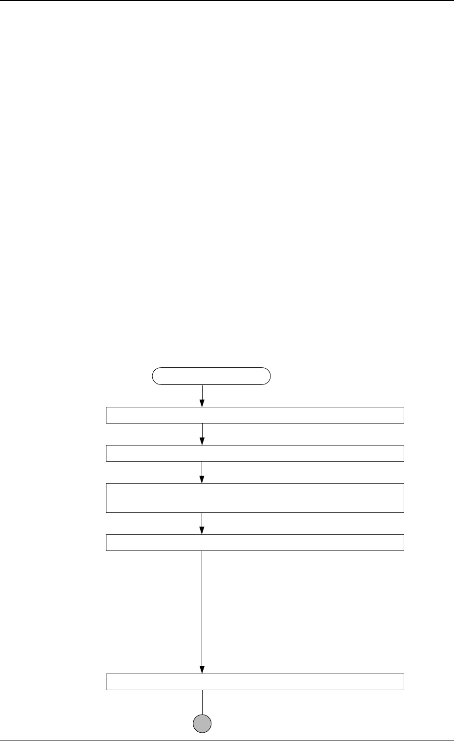
Teaching Procedure
Designate the objective feeder No. for teaching.
Select the [TEACH PICK-UP POS. [COMP. CENTER POS.]] key.
Select the [CENTER 1-PT.] key or perform the “DIAGONAL
2-PT” operation.
Press the [MOVE] button.
The placement head moves to the objective
feeder position for teaching and the image of
the pick-up location is captured by the P.E.C.
recognition camera.
When the [CENTER 1-PT.] key is selected,
the registration of the designated nozzle is made
together for graphic teaching to facilitate the
manual alignment operation with the trackball.
Positioning Operation with Trackball
Refer to “Trackball Operation” (described
later) for details.
3-106
6.10 PICK-UP LOCATION (TAPE·VIB. STICK) Display
Fig. 4C188
0305-001 Tg0860-PM-MM
• Teaching Operation for Setting of Eccentric Pick-Up against Hindrance
to Component Picks at Center
(1) Follow the teaching flow in Fig. 4C188 and perform the teaching opera-
tion on the component center position.
(2) Follow the teaching flow in Fig. 4C189 and perform the teaching opera-
tion on the pick-up location correction position.
When a component has a groove, a protrusion, etc., and cannot be picked
up at the center without any hindrance, use the [TEACH ECC. PICKUP
POS [PICKUP LOC. ADJ] key.
Before teaching the data for “PICKUP LOCATION ADJUSTMENT” in
the component library data to intentionally shift the pick-up location from
the component center, it is premised that the component center position
should be grasped first. Therefore, be sure to select the [TEACH PICK-
UP POS. [COMP. CENTER POS.]] key and perform the teaching op-
eration on the component center position. After that, select the [TEACH
ECC. PICKUP POS [PICKUP LOC. ADJ]] key to adjust the pick-up
location.
Note: When the center position is not grasped correctly and the teaching
operation is performed on the eccentric pick-up location, improper
values are fed back to “PICKUP LOCATION ADJUSTMENT
X, Y”, causing the component library data to lose its generality.
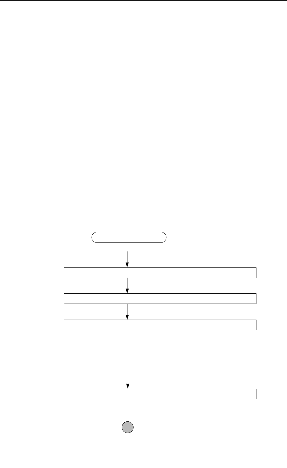
Teaching Procedure
Designate the objective feeder No. for teaching.
Select the [TEACH ECC. PICKUP POS [PICKUP LOC. ADJ] key.
Press the [MOVE] button.
An image is captured by the P.E.C. camera at
the pick-up location correction position of the
objective feeder for teaching.
The pick-up location adjustment data set up at
teaching execution is reflected.
Positioning Operation with Trackball
Refer to “Trackball Operation” (described
later) for details.
3-107
6.10 PICK-UP LOCATION (TAPE·VIB. STICK) Display
Fig. 4C189
0305-001 Tg0860-PM-MM
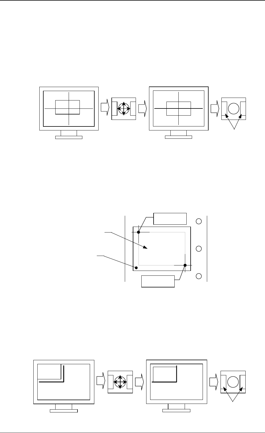
• Trackball Operation
[CENTER 1-PT.] Key
The cross hairs appear on the recognition monitor.
Adjust the cross hairs to the pick-up point, using the trackball.
(1) When the [CENTER 1-PT.] key is selected and the [MOVE] button is
pressed, the P.E.C. recognition camera moves to the designated feeder
No. position.
(2) Manipulate the trackball as shown in the following figure.
“DIAGONAL 2-PT.”
Specify the two edges of the component to be picked up or the embossed
mounting hole.
Specify the edge two points of the component in embossed.
Or, specify two corners (points) of the embossed mounting hole.
(1) When the [1POINT] key is selected and the [MOVE] button is pressed,
the P.E.C. recognition camera moves to the designated feeder No. posi-
tion.
“ (first point)” appears on the recognition monitor.
(2) Make an alignment with the trackball and press the right and left buttons
simultaneously.
3-108
6.10 PICK-UP LOCATION (TAPE·VIB. STICK) Display
Fig. 4C190
Fig. 4C191
Fig. 4C192
Press the buttons
simultaneously.
Roll the ball for
alignment.
Trackball
Trackball
Crosshairs dislocated from the
pick-up point
Second Point
First Point
Component
Embossed
Mounting Hole
Roll the ball for
alignment.
Trackball
Trackball
Press the buttons
simultaneously.