4OM-1011-002.pdf - 第166页
0305-001 Tg0860-PM-MM *10 “ALL BEAM ZERO” When all beams are zeroed completely , the background turns green. Otherwise, the background has no color . Note: When the teaching operation is performed with all beams not zero…
0305-001 Tg0860-PM-MM
*c “STEP #”
When “FEEDER #” in *b is selected, the step
No. where the feeder No. is registered is dis-
played.
When the feeder No. selected in *b is allo-
cated to several steps, the currently displayed
step No. can be changed by pressing the [ ]
or the [ ] key.
*d “BLOCK #”
When *b and *c are selected, the block No.
where the feeder No. is registered is displayed.
When the identical feeder Nos. are set in sev-
eral blocks in accordance with the feeder and
step Nos. selected in *b and *c, the block No.
can be changed by pressing the [ ] or the
[ ] key after the key beside “BLOCK #” is
selected.
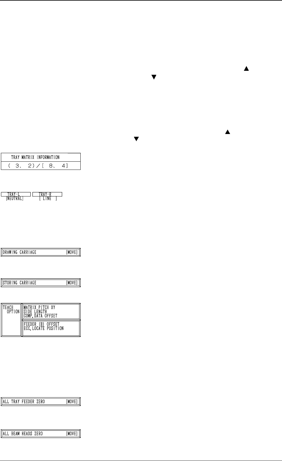
*3 “TRAY MATRIX INFORMATION” (X, Y)/(X, Y)
Displayed are the coordinates (X, Y) representing from
which tray in the specified block the components must be
picked up first and the matrices (X, Y) specified in the com-
ponent library data.
*4 “TRAY-L” and “TRAY-R”
It is shown which mode “[NEUTRAL], [LINE], or [LO-
CAL]” the right and left multi-layer tray feeders are in and
whether they are zeroed or not.
When the multi-layer tray feeder is zeroed, “” appears.
Note: The condition of the disconnected multi-layer tray
feeder is not shown.
*5 [DRAWING CARRIAGE [MOVE]] Key
When this key is selected and the [MOVE] button is pressed,
the pallet related to the specified feeder No. and step is
drawn out.
*6 [STORING CARRIAGE [MOVE]] Key
When this key is selected and the [MOVE] button is pressed,
the drawn pallet is stored in the magazine.
*7 “TEACH OPTION”
[MATRIX PITCH XY SIDE LENGTH COMP. DATA OFF-
SET] Key
When this key is pressed, the display (Fig. 4C220) ap-
pears on the screen, enabling the teaching operation of
the matrix pitch X and Y, the side length, and the compo-
nent data offset.
[FEEDER (B) OFFSET ECC. LOCATE POSITION]
Key
When this key is pressed, the display (Fig. 4C231) ap-
pears on the screen, enabling the teaching operation of
the feeder (B) offset and the eccentric pick-up position.
*8 [ALL TRAY FEEDER ZERO [MOVE]] Key
This key is used to zero all multi-layer tray feeders..
When this key is selected and the [MOVE] button is pressed,
the zeroing operation starts.
*9 [ALL BEAM HEADS ZERO] Key
This key is used to zero both Beams A and B.
When this key is selected and the [MOVE] button is pressed,
the zeroing operation starts.
6.12 PICK-UP LOCATION (TRAY) Display (Option)
3-114
Fig. 4C209
Fig. 4C210
Fig. 4C211
Fig. 4C212
Fig. 4C213
Fig. 4C214
Fig. 4C215

0305-001 Tg0860-PM-MM
*10 “ALL BEAM ZERO”
When all beams are zeroed completely, the background
turns green. Otherwise, the background has no color.
Note: When the teaching operation is performed with all
beams not zeroed completely, the offset values may
not be taught correctly.
*11 “RECOG. COMM.”
When “DISABLE” is set in the “P.E.C.” and “COMPO
NENT RECOGNITION” data boxes at the “TEST
MODE” display, the background color of “P.E.C. RECOG.”
and “COMP. RECOG.” becomes light red. (No background
color in normal cases)
*12 [COMPONENT LIBRARY EDIT] Key
When this key is pressed, the “COMPONENT LIBRARY
EDIT” display appears on the screen, enabling the opera
tor to edit the data related to the feeder No. which was
selected in *1.
Operation Procedure
(1) Confirm that “ALL BEAM ZERO” is displayed.
(2) Confirm that the multi-layer tray feeder is set in the
“LINE” mode and located at its origin.
(3) Select the tray carriage to be taught and perform the set-
ting of the feeder.
(4) Select the [DRAWING CARRIAGE [MOVE]] key and
press the [MOVE] button.
(5) Select the item to be taught and perform the teaching
operation.
Refer to the operation procedures in “6.12.1 MATRIX
PITCH XY・SIDE LENGTH・LOC. OFFSET Display
(Option)” and “6.12.2 FEEDER (B) OFFSET・ECC. LO-
CATE OFFSET Display (Option)” for details.
(6) After the teaching operation is completed, select the
[STORING CARRIAGE [MOVE]] key and press the
[MOVE] button.
3-115
6.12 PICK-UP LOCATION (TRAY) Display (Option)
Fig. 4C216
Fig. 4C217
Fig. 4C218
0305-001 Tg0860-PM-MM
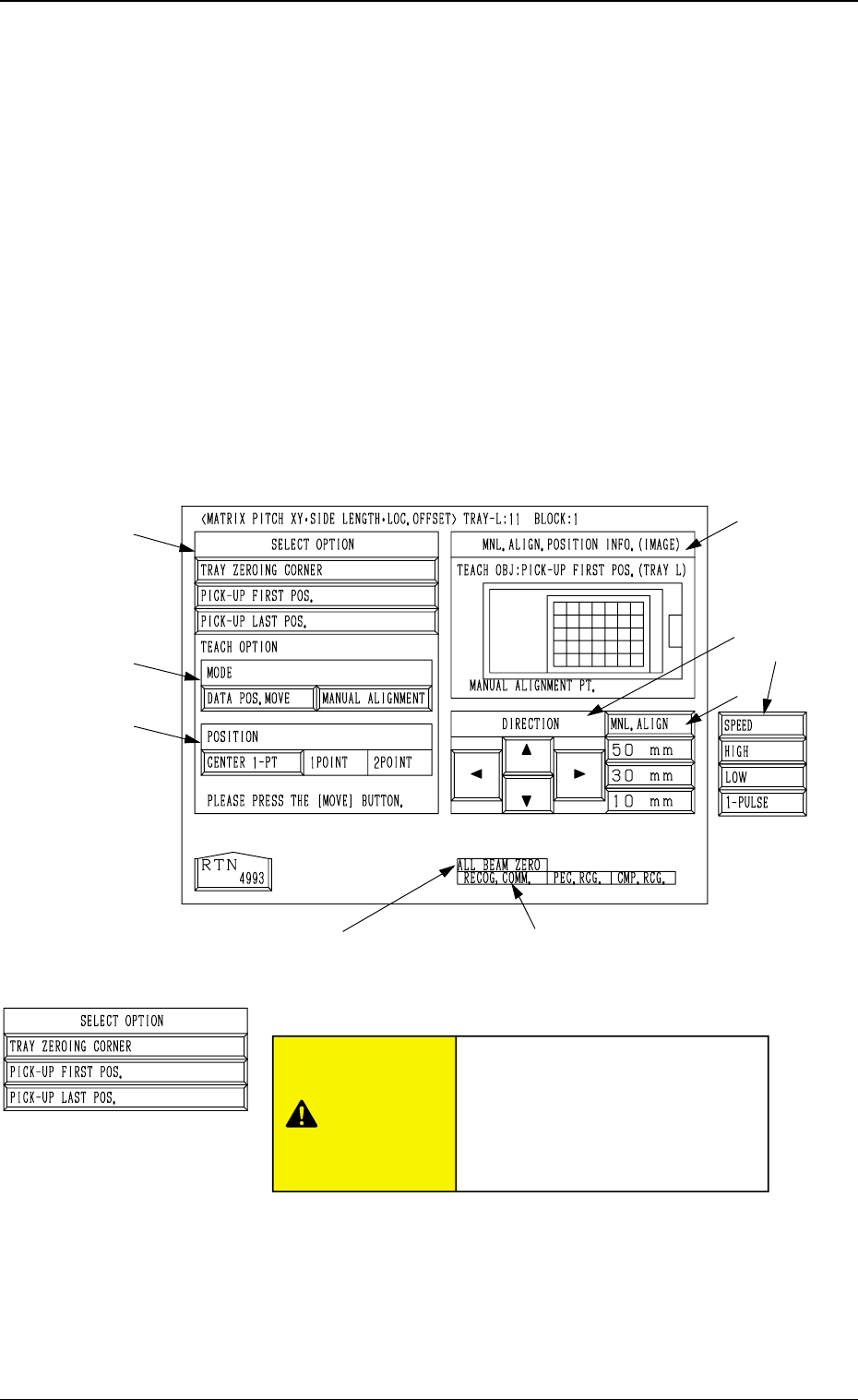
• This display allows the teaching operation on the matrix pitch X and Y, the side length, and
the component data offset of the tray.
Described in this session is mainly how to teach the component library data items. The next
session “Teaching Operation of Feeder (B) Offset” describes how to teach the pick-up
position at each step when the same types of components (the same library data) are used in
several steps of the magazine.
This teaching operation is performed on each component library data.
Note: Before performing the teaching operation, be sure to confirm that correct param-
eters are set in the “X” and “Y” data boxes of the label “MATRIX” in the compo-
nent library data of the pertinent tray.
If incorrect parameters are set, the pitch data cannot be calculated correctly.
When the [MATRIX PITCH XY SIDE LENGTH COMP. DATA OFFSET] key is pressed
at the “PICK-UP LOCATION (TRAY)” display, the following display appears on the screen.
Note: The graphic looks different when the recognition monitor is installed on the Beam A
side (option).
*1 “SELECT OPTION”
[TRAY ZEROING CORNER] Key
When this key is pressed, the teaching operation is per-
formed on the tray zeroing corner.
The teaching operation is performed on the tray zeroing
corner through manual alignment to calculate the tray
positional offset (“X (mm)” and “Y (mm)” of “OFF-
SET” in the component data (“Tray Steps Information”).
*8 *9
3-116
6.12 PICK-UP LOCATION (TRAY) Display (Option)
*1
*2
*3
*7
*5
*4
*6
Fig. 4C219
6.12.1 MATRIX PITCH XY·SIDE LENGTH·LOC. OFFSET
Display (Option)
Fig. 4C220
CAUTION
“TRAY DATA” in the component
library data is modified addition-
ally.
Incorrect teaching operation will
cause an error in component
picks.