4OM-1011-002.pdf - 第170页
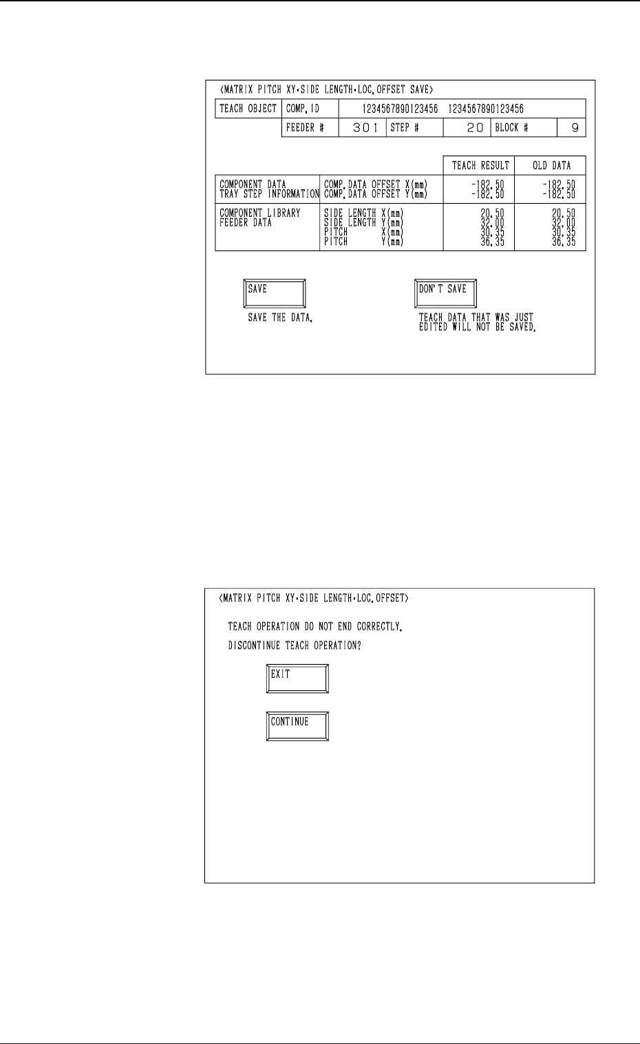
0305-001 Tg0860-PM-MM (12) When the teaching operation on the three items is com- pleted, the following display appears on the screen. (13) Check the data and determine whether it should be saved or not. • When the [SA V…
0305-001 Tg0860-PM-MM
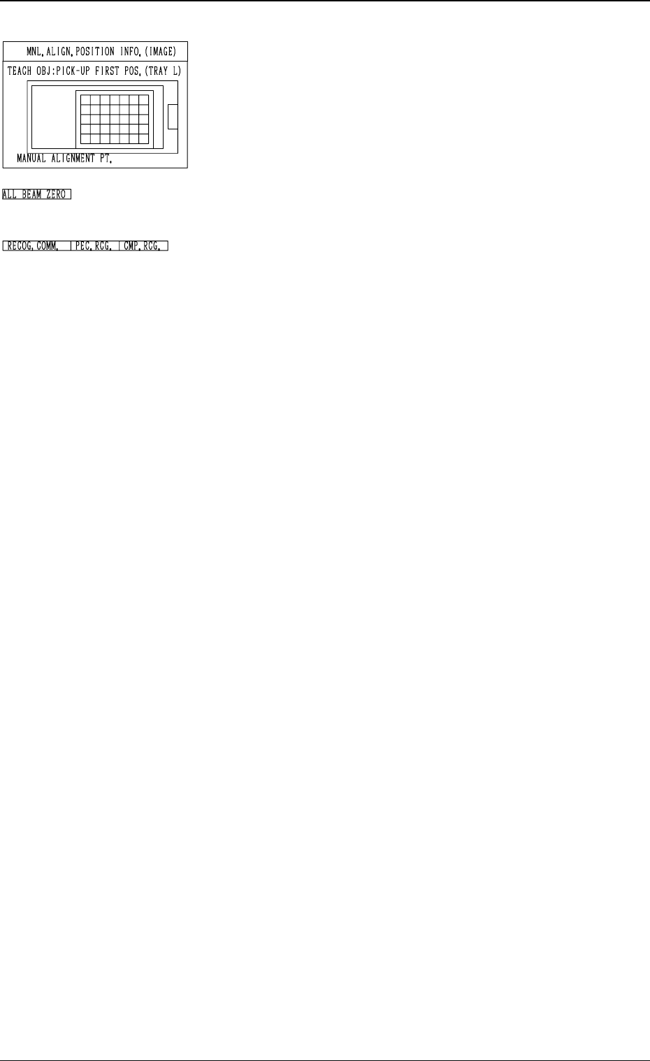
*7 “MNL. ALIGN. POSITION INFO. (IMAGE)”
Displayed is the image of the manually aligned position.
The red cross indicates the manually aligned position.
*8 “ALL BEAM ZERO”
When all beams are zeroed completely, the background turns
green. Otherwise, the background has no color.
*9 “RECOG. COMM.”
When “DISABLE” is set in the “P.E.C.” and “COMPO-
NENT RECOGNITION” data boxes at the “TEST
MODE” display, the background color of “P.E.C. RECOG.”
and “COMP. RECOG.” becomes light red. (No background
color in normal cases)
Operation Procedure
Note: Before performing the teaching operation, be sure to
confirm that correct parameters are set in the “X”
and “Y” data boxes of the label “MATRIX” in the
component library data of the pertinent tray.
If incorrect parameters are set, the pitch data cannot
be calculated correctly.
(1) Confirm that “ALL BEAM ZERO” is displayed.
(2) Select the [TRAY ZEROING CORNER] key.
(3) Select the [CENTER 1-PT] key.
(4) Select the [DATA POS. MOVE] key.
The P.E.C. recognition camera moves to the specified
position.
(5) Confirm that the origin position of the tray (tray corner) is
on the recognition monitor.
When the origin position of the tray is not displayed, ad-
just it with one of the “MNL. ALIGN” or the “SPEED”
keys.
(6) Select the [MANUAL ALIGNMENT] key and press the
[MOVE] button.
Proceed to the trackball operation and perform the manual
alignment.
Refer to “Trackball Operation in 6.10 PICK-UP LOCA-
TION (TAPE・VIB. STICK) Display” for details.
(7) Select the [PICK-UP FIRST POS.] Key.
(8) Select one of the “POSITION” keys and then the [DATA
POS. MOVE] key.
(9) Confirm that the first component in the tray matrix is dis-
played on the recognition monitor.
Otherwise, adjust it with one of the “MNL. ALIGN” or
the “SPEED” keys.
(10) Select the [MANUAL ALIGNMENT] key and press the
[MOVE] button. Proceed to the trackball operation and
perform the manual alignment.
(11) Select the [PICK-UP LAST POS.] key.
Follow the procedure similar to “PICK-UP FIRST POS.”
and perform the teaching operation.
3-118
6.12 PICK-UP LOCATION (TRAY) Display (Option)
Fig. 4C226
Fig. 4C227
Fig. 4C228
0305-001 Tg0860-PM-MM
(12) When the teaching operation on the three items is com-
pleted, the following display appears on the screen.
(13) Check the data and determine whether it should be saved
or not.
• When the [SAVE] key is selected, the data is saved
and the display (Fig. 4C206) appears on the screen.
• When the [DON’T SAVE] key is selected, the data is
not saved and the display (Fig. 4C206) appears on the
screen.
• When the teaching operation on the three items is not com-
pleted and the [RTN] key is pressed, the following display
appears on the screen.
Enabling the operator to decide whether or not the teaching
operation should be interrupted.
• When the [EXIT] key is selected, the results of the teach-
ing operation are not reflected and the display (Fig. 4C206)
appears on the screen.
• When the [CONTINUE] key is selected, the display (Fig.
4C219) appears on the screen, enabling the operator to con-
tinue the teaching operation.
3-119
6.12 PICK-UP LOCATION (TRAY) Display (Option)
Fig. 4C229
Fig. 4C230
0305-001 Tg0860-PM-MM
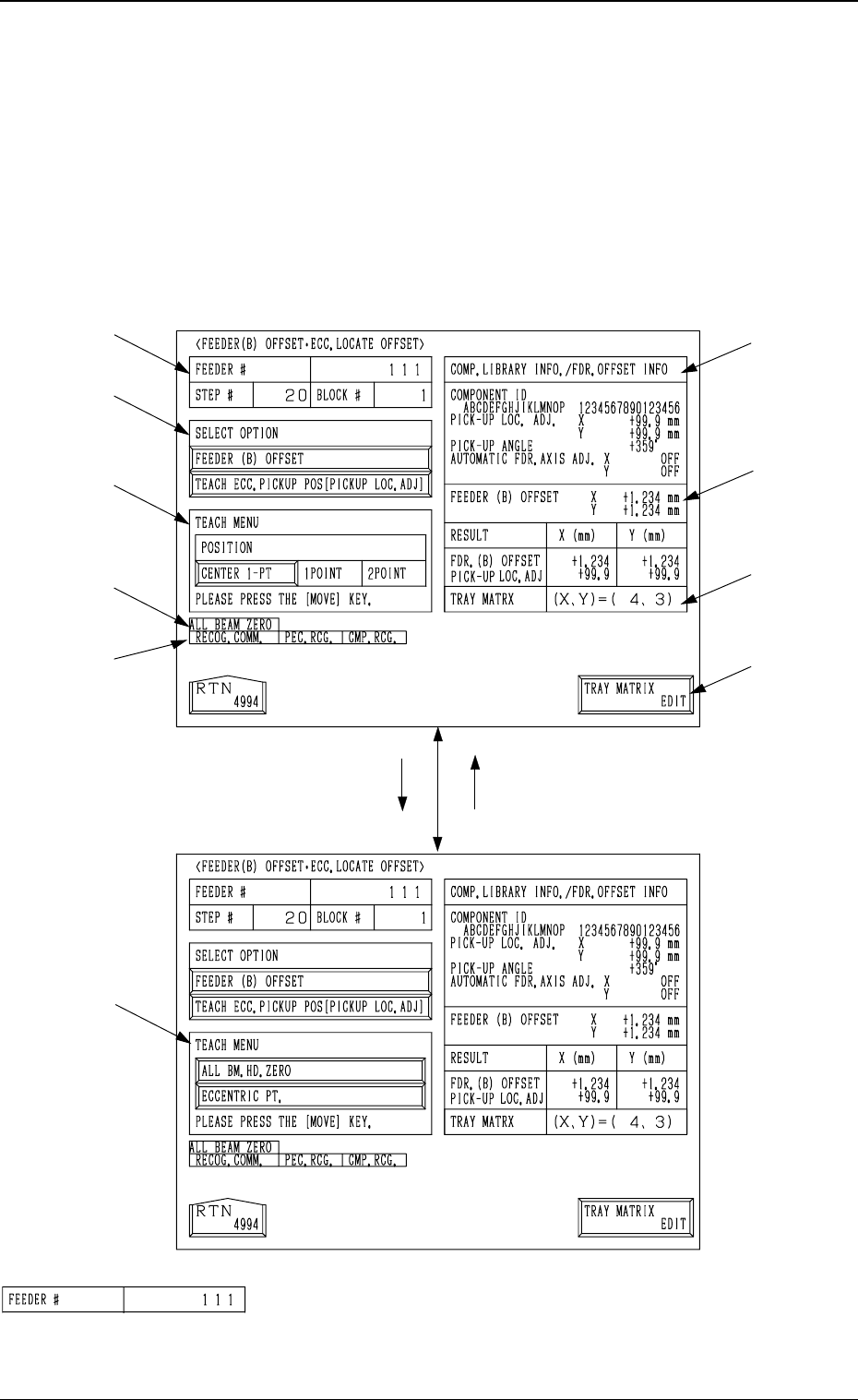
6.12.2 FEEDER (B) OFFSET
••
••
•
ECC. LOCATE OFFSET
Display (Option)
• This display allows the teaching operation on the feeder (B) offset and ec-
centric pick-up location of the multi-layer tray feeder (option).
When the [FEEDER (B) OFFSET ECC. LOCATE POSITION] key is pressed
at the “PICK-UP LOCATION (TRAY)” display, the following display appears
on the screen.
*1 “FEEDER #”
Shown is the feeder No. which was specified at the display
(Fig. 4C206).
[TEACH ECC. PICKUP POS
[PICKUP LOC. ADJ]] Key
[FEEDER (B) OFFSET] Key
*1
*2
*3
*9
*10
*4
*5
*6
*7
*8
3-120
6.12 PICK-UP LOCATION (TRAY) Display (Option)
Fig. 4C231
Fig. 4C232
Fig. 4C233