4OM-1011-002.pdf - 第174页
0305-001 Tg0860-PM-MM 6.12.3 PICK-UP LOCA TION TEACH - TRA Y MA TRIX EDIT Display (Option) • This display allows the editing of the pick-up matrices. When the [TRA Y MA TRIX EDIT] key is pressed at the "FEEDER (B) O…
0305-001 Tg0860-PM-MM
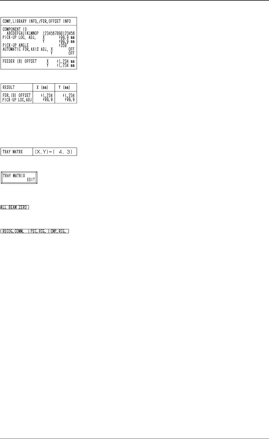
*5 “COMP. LIBRARY INFO./FDR. OFFSET INFO”
Displayed are the component library data and the feeder
offset of the feeder No. set up in *1.
*6 “RESULT X (mm), Y (mm)”
When the manual alignment operation (using the trackball)
is completed, the results of the teaching operation are dis-
played.
Selection of [FEEDER (B) OFFSET] Key: FEEDER (B)
OFFSET
Selection of [TEACH ECC. PICKUP POS [PICKUP LOC.
ADJ]] Key: PICK-UP LOCATION ADJUSTMENT
*7 “TRAY MATRIX”
Shown are the coordinates (X, Y) which represent the pick-
up matrices of the selected tray.
*8 [TRAY MATRIX EDIT] Key
When this key is pressed, the display (Fig. 4C243) appears
on the screen.
Use this function to edit the pick-up matrices.
*9 “ALL BEAM ZERO”
When all beams are zeroed completely, the background turns
green. Otherwise, the background has no color.
*10 “RECOG. COMM.”
When “DISABLE” is set in the “P.E.C.” and “COMPO
NENT RECOGNITION” data boxes at the “TEST
MODE” display, the background color of “P.E.C. RECOG.”
and “COMP. RECOG.” becomes light red.
(No background color in normal cases)
Operation Procedure
Refer to “6.10 PICK-UP LOCATION (TAPE・VIB.
STICK) Display” for details.
3-122
6.12 PICK-UP LOCATION (TRAY) Display (Option)
Fig. 4C237
Fig. 4C238
Fig. 4C239
Fig. 4C240
Fig. 4C241
Fig. 4C242
0305-001 Tg0860-PM-MM
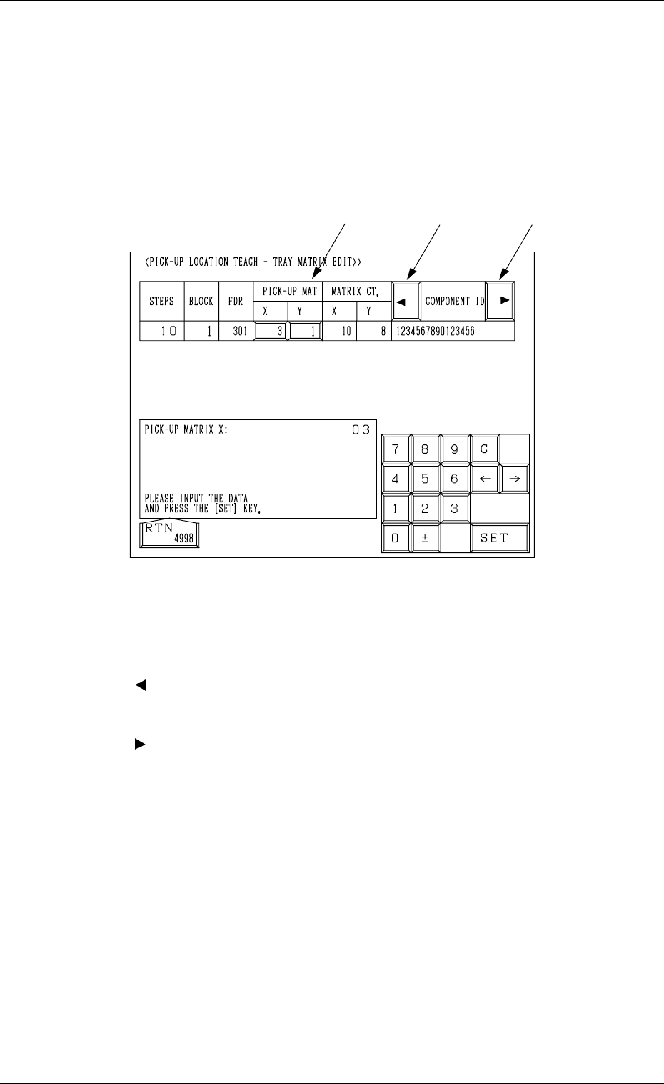
6.12.3 PICK-UP LOCATION TEACH - TRAY MATRIX EDIT
Display (Option)
• This display allows the editing of the pick-up matrices.
When the [TRAY MATRIX EDIT] key is pressed at the "FEEDER (B)
OFFSET・ECC. LOCATE OFFSET" display, the following display appears on
the screen.
*1 “PICK-UP MAT X, Y”
The pick-up matrices X and Y can be changed.
*2 [ ] Key
When this key is pressed, the “COMPONENT ID” field shifts horizontally
to the left, enabling you to view the first part of component IDs.
*3 [ ] Key
When this key is pressed, the “COMPONENT ID” field shifts horizontally
to the right, enabling you to view the comments.
Operation Procedure
(1) Select the key under “X” or “Y”.
(2) Specify the matrix position, using the ten-key pad.
(3) Press the [SET] key.
3-123
6.12 PICK-UP LOCATION (TRAY) Display (Option)
*1
*2
*3
Fig. 4C243
0305-001 Tg0860-PM-MM
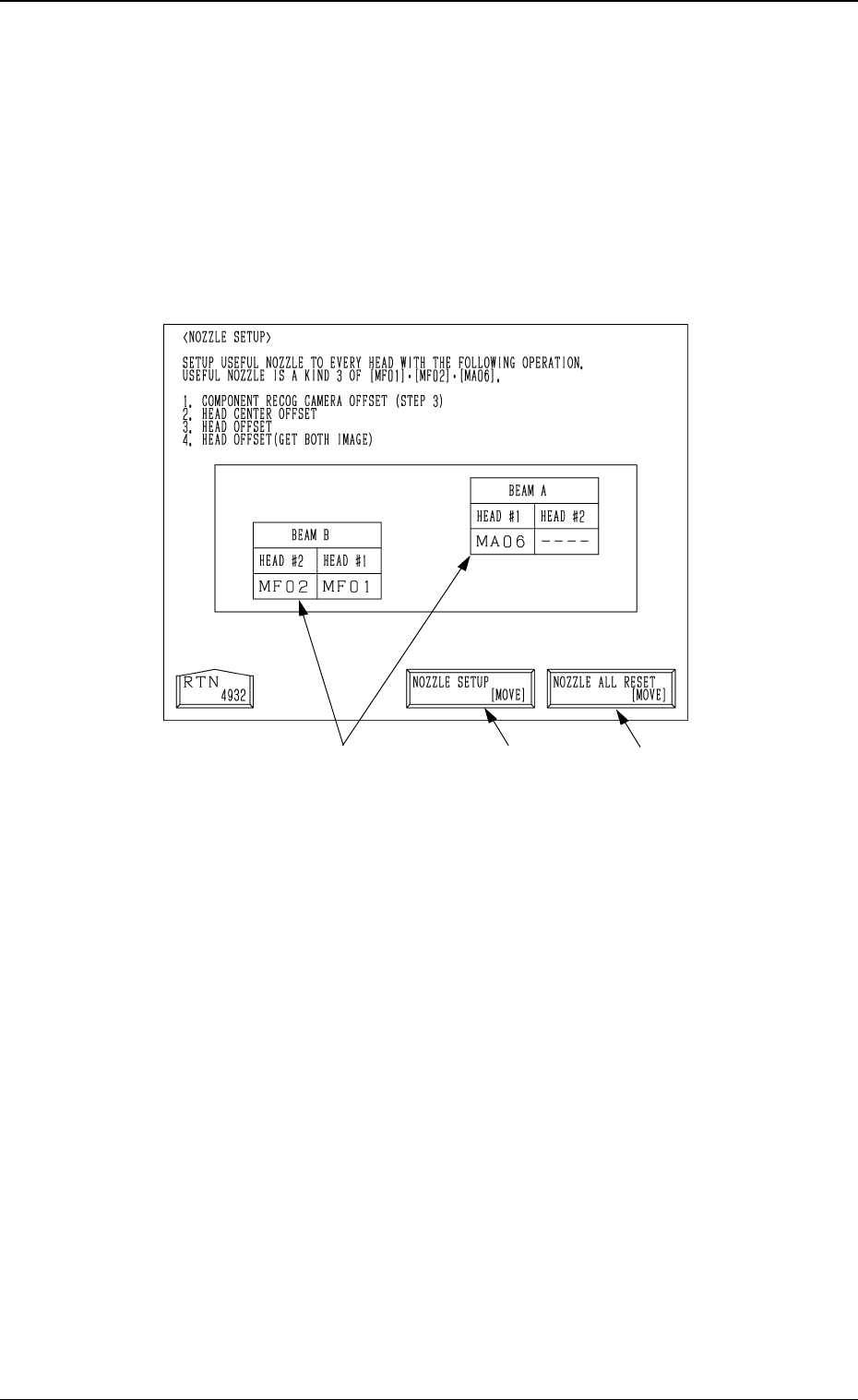
6.13 Nozzle Setup
• This function automatically mounts the nozzles to be used in teaching opera-
tions on each head.
When the [NOZZLE SETUP] key is pressed at the “TEACH OFFSET” dis-
play, the following display appears on the screen.
*1
Fig. 4C244
3-124
6.13 Nozzle Setup
*2
*1 [NOZZLE SETUP [MOVE]]
When the [MOVE] button is pressed after selecting this key, all the
nozzles mounted on heads are housed in the nozzle stockers, and then the
nozzles [MF01], [MF02] and [MA06] are mounted on each head.
*2 [NOZZLE ALL RESET (MOVE)]
When the [MOVE] button is pressed after selecting this key, all the nozzles
mounted on heads are housed in the nozzle stockers.
*3 Nozzle Mounting Condition
The nozzle mounting condition on each head is displayed.
Operation Procedure
(1) Set the nozzles [MF01], [MF02] and [MF06] in the nozzle stockers.
(2) Select the [NOZZLE SETUP (MOVE)] key and then press the [MOVE]
button.
*3