4OM-1011-002.pdf - 第175页
0305-001 Tg0860-PM-MM 6.13 Nozzle Setup • This function automatically mounts the nozzles to be used in teaching opera- tions on each head. When the [NOZZLE SETUP] key is pressed at the “TEACH OFFSET” dis- play , the foll…
0305-001 Tg0860-PM-MM
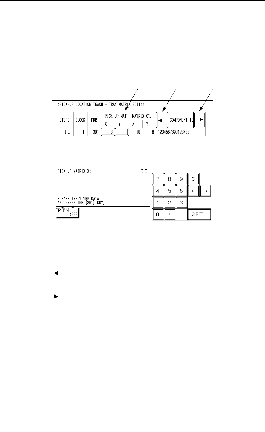
6.12.3 PICK-UP LOCATION TEACH - TRAY MATRIX EDIT
Display (Option)
• This display allows the editing of the pick-up matrices.
When the [TRAY MATRIX EDIT] key is pressed at the "FEEDER (B)
OFFSET・ECC. LOCATE OFFSET" display, the following display appears on
the screen.
*1 “PICK-UP MAT X, Y”
The pick-up matrices X and Y can be changed.
*2 [ ] Key
When this key is pressed, the “COMPONENT ID” field shifts horizontally
to the left, enabling you to view the first part of component IDs.
*3 [ ] Key
When this key is pressed, the “COMPONENT ID” field shifts horizontally
to the right, enabling you to view the comments.
Operation Procedure
(1) Select the key under “X” or “Y”.
(2) Specify the matrix position, using the ten-key pad.
(3) Press the [SET] key.
3-123
6.12 PICK-UP LOCATION (TRAY) Display (Option)
*1
*2
*3
Fig. 4C243
0305-001 Tg0860-PM-MM
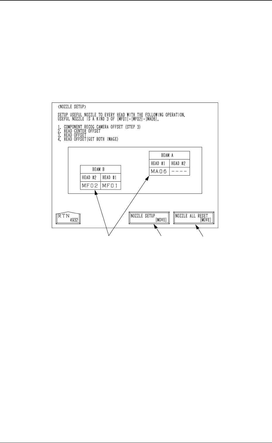
6.13 Nozzle Setup
• This function automatically mounts the nozzles to be used in teaching opera-
tions on each head.
When the [NOZZLE SETUP] key is pressed at the “TEACH OFFSET” dis-
play, the following display appears on the screen.
*1
Fig. 4C244
3-124
6.13 Nozzle Setup
*2
*1 [NOZZLE SETUP [MOVE]]
When the [MOVE] button is pressed after selecting this key, all the
nozzles mounted on heads are housed in the nozzle stockers, and then the
nozzles [MF01], [MF02] and [MA06] are mounted on each head.
*2 [NOZZLE ALL RESET (MOVE)]
When the [MOVE] button is pressed after selecting this key, all the nozzles
mounted on heads are housed in the nozzle stockers.
*3 Nozzle Mounting Condition
The nozzle mounting condition on each head is displayed.
Operation Procedure
(1) Set the nozzles [MF01], [MF02] and [MF06] in the nozzle stockers.
(2) Select the [NOZZLE SETUP (MOVE)] key and then press the [MOVE]
button.
*3
0305-001 Tg0860-PM-MM
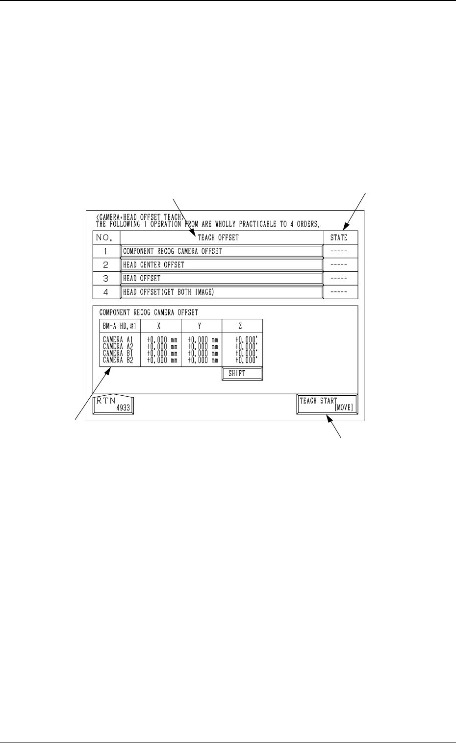
6.14 Camera Head Offset
• The following teaching operations can be performed at the same time.
Component Recog Camera Offset (Step-3)
Head Center Offset
Head Offset
Head Offset (Get Both Image)
When the [CAMERA
•
HEAD OFFSET] key is pressed at the “TEACH
OFFSET” display, the following display appears on the screen.
6.14 Camera Head Offset
Fig. 4C245
3-125
*1
*3
*2
*4
*1 [TEACH START [MOVE]]
When the [MOVE] button is pressed after selecting this key, the following
teaching operations are performed one after another.
Component Recog Camera Offset (Step-3)
Head Center Offset
Head Offset
Head Offset (Get Both Image)
*2 “TEACH OFFSET”
The progress status of each teaching operation is indicated.
*3 “STATE”
The nozzle mounting condition on each head is displayed.
“---” : The progress status is indicated before the teaching
operation is performed.
“RUN” : The progress status is indicated during the teaching
operation.
“COMPLETE” : It is indicated when the teaching operation is completed.