4OM-1011-002.pdf - 第177页
0305-001 Tg0860-PM-MM *4 Date Indication When the [TEACH OFFSET] key is pressed, each offset data is indicated. In the case of “COMPONENT RECOG. CAMERA OFFSET”, pressing the [SHIFT] key indicates the data for each head i…
0305-001 Tg0860-PM-MM
6.14 Camera Head Offset
• The following teaching operations can be performed at the same time.
Component Recog Camera Offset (Step-3)
Head Center Offset
Head Offset
Head Offset (Get Both Image)
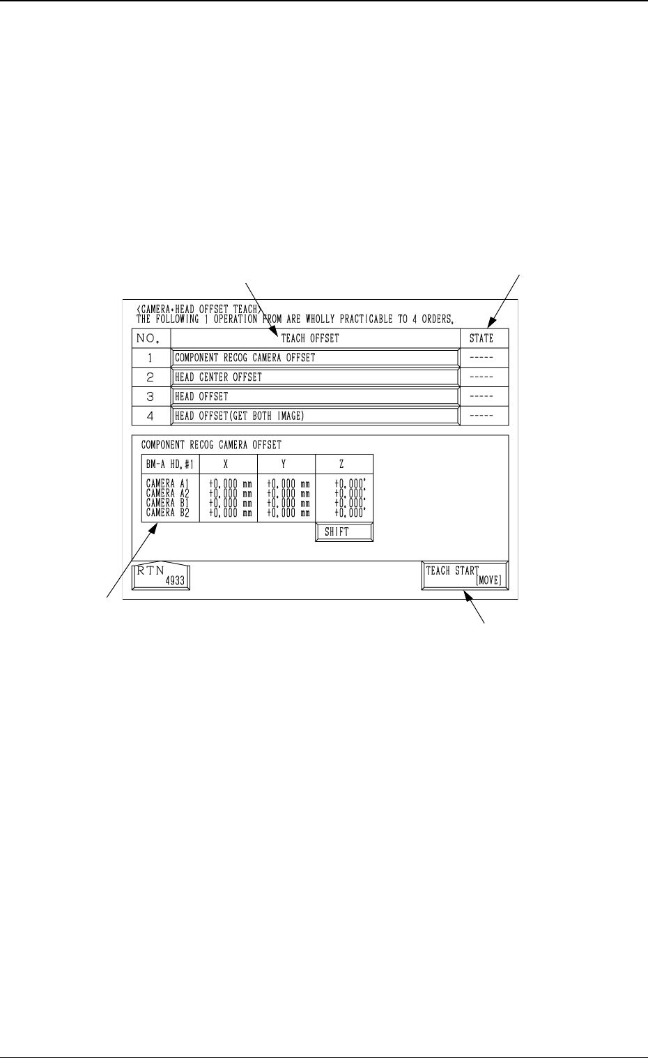
When the [CAMERA
•
HEAD OFFSET] key is pressed at the “TEACH
OFFSET” display, the following display appears on the screen.
6.14 Camera Head Offset
Fig. 4C245
3-125
*1
*3
*2
*4
*1 [TEACH START [MOVE]]
When the [MOVE] button is pressed after selecting this key, the following
teaching operations are performed one after another.
Component Recog Camera Offset (Step-3)
Head Center Offset
Head Offset
Head Offset (Get Both Image)
*2 “TEACH OFFSET”
The progress status of each teaching operation is indicated.
*3 “STATE”
The nozzle mounting condition on each head is displayed.
“---” : The progress status is indicated before the teaching
operation is performed.
“RUN” : The progress status is indicated during the teaching
operation.
“COMPLETE” : It is indicated when the teaching operation is completed.

0305-001 Tg0860-PM-MM
*4 Date Indication
When the [TEACH OFFSET] key is pressed, each offset data is indicated.
In the case of “COMPONENT RECOG. CAMERA OFFSET”, pressing
the [SHIFT] key indicates the data for each head in turn.
Operation Procedure
(1) Select the [CAMERA
•
HEAD OFFSET] key and press the [MOVE]
button. The offsets of Nos. 1 to 4 are automatically taught in turn.
Note: In the following cases, the “CAMERA
•
HEAD OFFSET” teaching
can’t be performed.
• If any one of the component recognition cameras is set to “Camera
Skip”.
• If any one of the heads is set to “Head Skip”.
3-126
6.14 Camera Head Offset
0305-001 Tg0860-PM-MM
7. DEVICE TEST Display
When the [DEVICE TEST] key is pressed at the “SPECIAL SEL.” display, the
following display appears on the screen.
*1 [P.E.C. RECOG TEST] Key
When this key is pressed, the “P.E.C. RECOG TEST” dis-
play opens,enabling the test and check operations (whether
or not P.E.C. recognition can be performed normally) of
fiducial mark recognition function.
Menus are provided to prepare for creation of recognition
mark data.
*2 [COMPONENT RECOG TEST] Key
When this key is pressed, the “COMPONENT RECOG.
TEST” display opens, enabling the check operation of cre-
ated component library data.
Menus are provided to make a test on component recogni-
tion and check whether or not the component designated
using a test ID can normally be recognized.
Note: When the [OPERATION/SET UP] switch is set to
the “SET UP” side, the device test operation can-
not be performed.
*3 [X/Y BEAM TEST] Key
When this key is pressed, the “X/Y BEAM TEST” display
appears on the screen, enabling the activation of only the
X/Y beam according to the current pattern program.
Menus are provide to check pattern program data and de-
termine operation start step No. of semi-automatic opera-
tion for continuous operation of the machine to complete
unfinished P.C.B.’s.
7. DEVICE TEST Display
3-127
Fig. 4C246
*1
*2
*3
Fig. 4C247
Fig. 4C248
Fig. 4C249