4OM-1011-002.pdf - 第181页
0305-001 Tg0860-PM-MM 7.1 P .E.C. RECOG TEST Display 3-130 There are two ways to move the X/Y beam to the position where the fiducial mark to be tested enters the visual field of the camera (window size). • The X/Y beam …
0305-001 Tg0860-PM-MM
*4 [P.E.C. RECOG TEST [MOVE]] Key
This key is used to perform the recognition test.
When this key is selected and the [MOVE] button is pressed,
the recognition test starts.
*5 [X/Y BEAM ZERO [MOVE]] Key
This key is used to finish the P.E.C. recognition test and
zero the X/Y beam.
When this key is selected and the [MOVE] button is pressed,
the X/Y beam is zeroed.
*6 [RESULT OF RECOG.] Key
When this key is pressed, the “RESULT OF P.E.C. REC-
OGNITION” display appears on the screen.
The result of recognition appears after the P.E.C. recogni-
tion test is performed.
7.1.1 X/Y BEAM MOVE Display
When the [X/Y BEAM MOVE] key is pressed at the “P.E.C. RECOG TEST”
display, the following display appears on the screen.
When the [DESIGNATED POSITION] key is pressed at the following display,
another “X/Y BEAM MOVE” display (Fig. 4C258) appears on the screen.
7.1 P.E.C. RECOG TEST Display
3-129
Fig. 4C257
Fig. 4C254
Fig. 4C255
Fig. 4C256
0305-001 Tg0860-PM-MM
7.1 P.E.C. RECOG TEST Display
3-130
There are two ways to move the X/Y beam to the position where the fiducial
mark to be tested enters the visual field of the camera (window size).
• The X/Y beam (the beam related to the parameter set in the “P.E.C. RECOG
CAMERA” data box at the “P.E.C. RECOG TEST” display (Fig. 4C250))
can be moved.
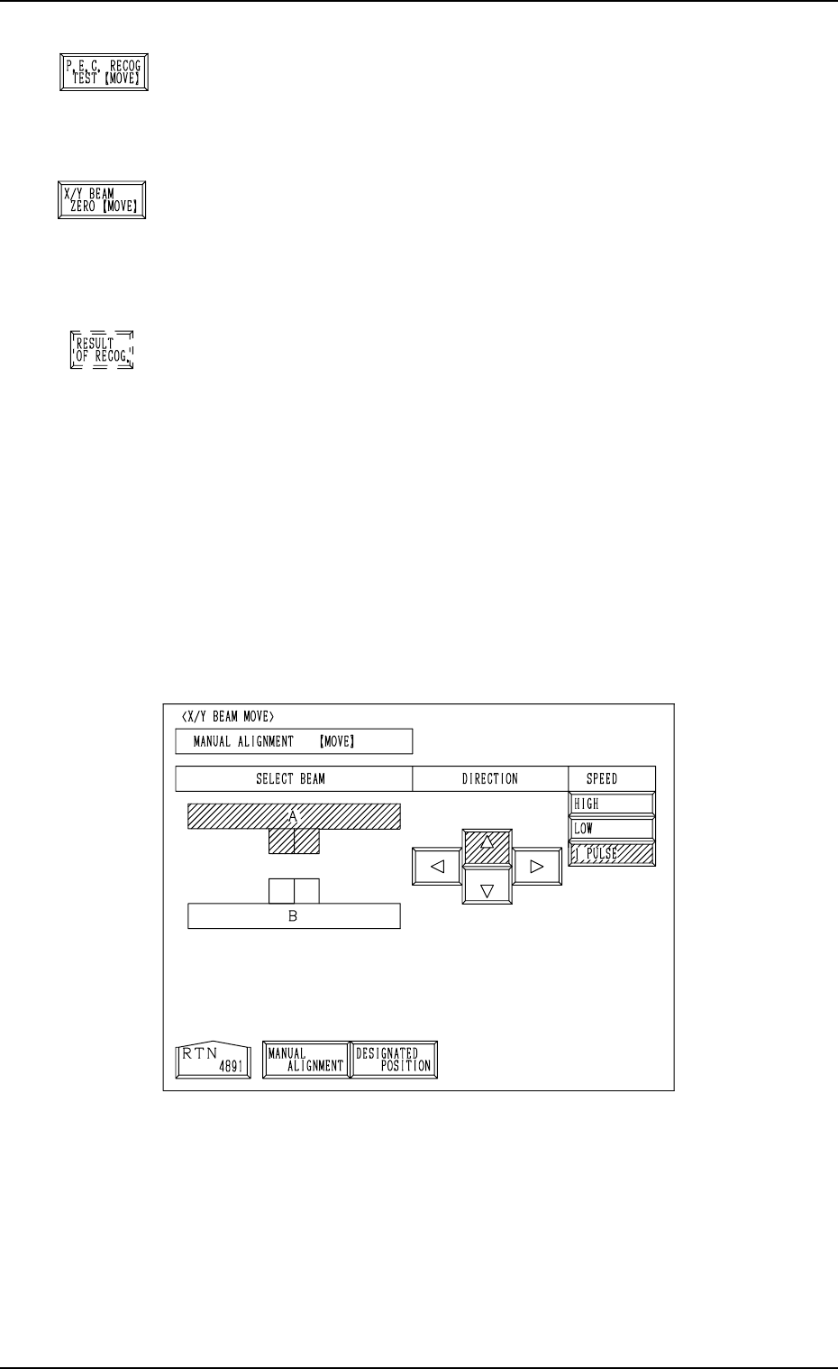
Manual Alignment Operation (Fig. 4C257)
(1) Press one of the “DIRECTION” keys to select a direction and select one
of the “SPEED” keys to specify the speed of the X/Y beam movement.
(2) When the [MOVE] button is pressed, the X/Y beam starts moving in the
designated direction at the specified speed.
While the [MOVE] button is kept pressed, the X/Y beam keeps on mov-
ing.
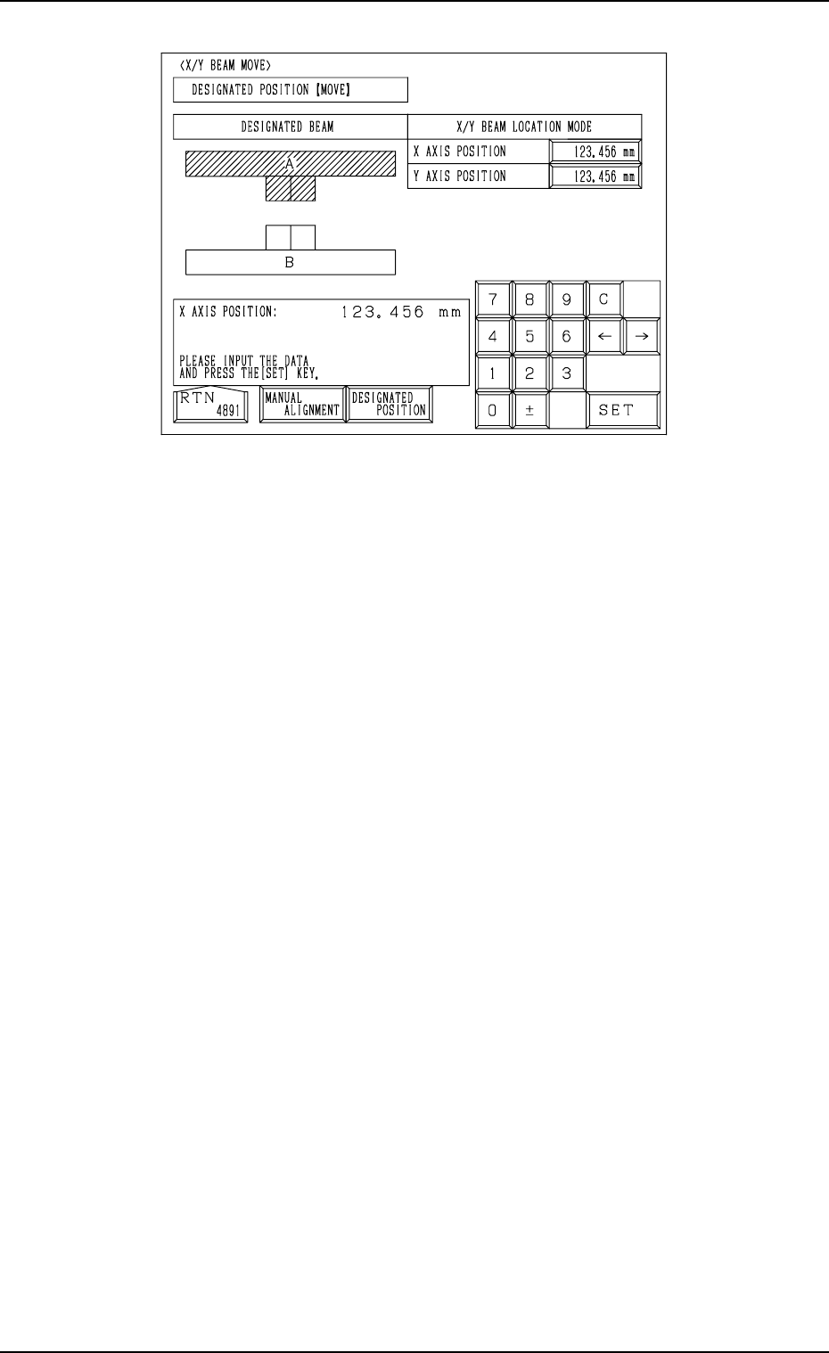
X/Y Beam Movement to Designated Position (Fig. 4C258)
(1) Select the “X AXIS POSITION” and “Y AXIS POSITION” data boxes
under the label “X/Y BEAM LOCATION MODE” and enter parameters
using the ten-key pad.
(2) When the [MOVE] button is pressed, the X/Y beam moves to the desig-
nated position.
Fig. 4C258
0305-001 Tg0860-PM-MM
7.1 P.E.C. RECOG TEST Display
3-131
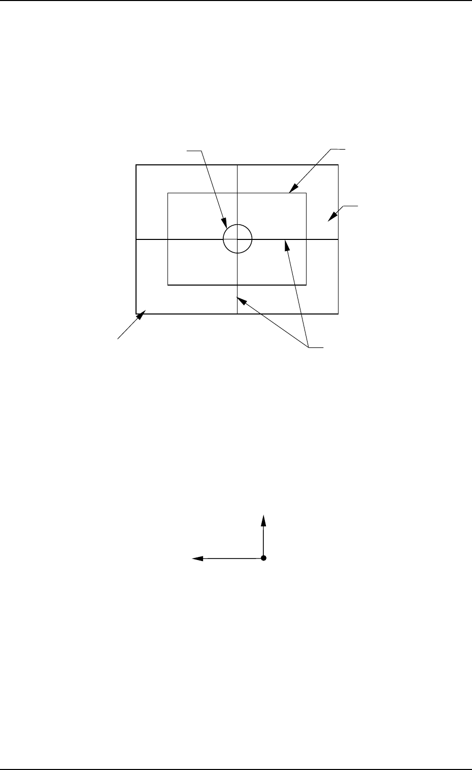
7.1.2 View on Recognition Monitor
When the “P.E.C. RECOG TEST” display is opened, a recognition range (win-
dow size) appears on the recognition monitor.
Note: When a window size is changed, the captured image also changes on
the recognition monitor.
●
OK Result of Recognition
The X/Y beam moves to the place where a fiducial mark is located at the
camera center and the outline of the mark shape and crosslines are displayed.
The positional deviation (X and Y) of the fiducial mark from the camera
center and the recognition time (TIME) are displayed in the A-marked area
of the window.
(The displayed positional deviation shows the deviation detected before test-
ing.)
Note: The point of intersection of the crosslines is the camera center.
• NG (No Good) Result of Recognition
The outline of mark shape and crosslines are not displayed and the “RE-
SULT OF P.E.C. RECOGNITION” display appears on the touch screen,
showing the result of recognition as “NO GOOD”.
Ref.: Pressing the [RESULT OF RECOG.] key at the “P.E.C. RECOG TEST”
display (Fig. 4C250) also opens the “RESULT OF P.E.C. RECOGNI-
TION” display.
Fig. 4C259
Window
(Recognition Area)
Recognition Range
(Window Size)
Crosslines
Image of Fiducial Mark
X=000 Y=000 TIME=000
A
Y (+)
X (+)
Camera Center
Fig. 4C260