4OM-1011-002.pdf - 第182页
0305-001 Tg0860-PM-MM 7.1 P .E.C. RECOG TEST Display 3-131 7.1.2 V iew on Recognition Monitor When the “P .E.C. RECOG TEST” display is opened, a recognition range (win- dow size) appears on the recognition monitor . Note…
0305-001 Tg0860-PM-MM
7.1 P.E.C. RECOG TEST Display
3-130
There are two ways to move the X/Y beam to the position where the fiducial
mark to be tested enters the visual field of the camera (window size).
• The X/Y beam (the beam related to the parameter set in the “P.E.C. RECOG
CAMERA” data box at the “P.E.C. RECOG TEST” display (Fig. 4C250))
can be moved.
Manual Alignment Operation (Fig. 4C257)
(1) Press one of the “DIRECTION” keys to select a direction and select one
of the “SPEED” keys to specify the speed of the X/Y beam movement.
(2) When the [MOVE] button is pressed, the X/Y beam starts moving in the
designated direction at the specified speed.
While the [MOVE] button is kept pressed, the X/Y beam keeps on mov-
ing.
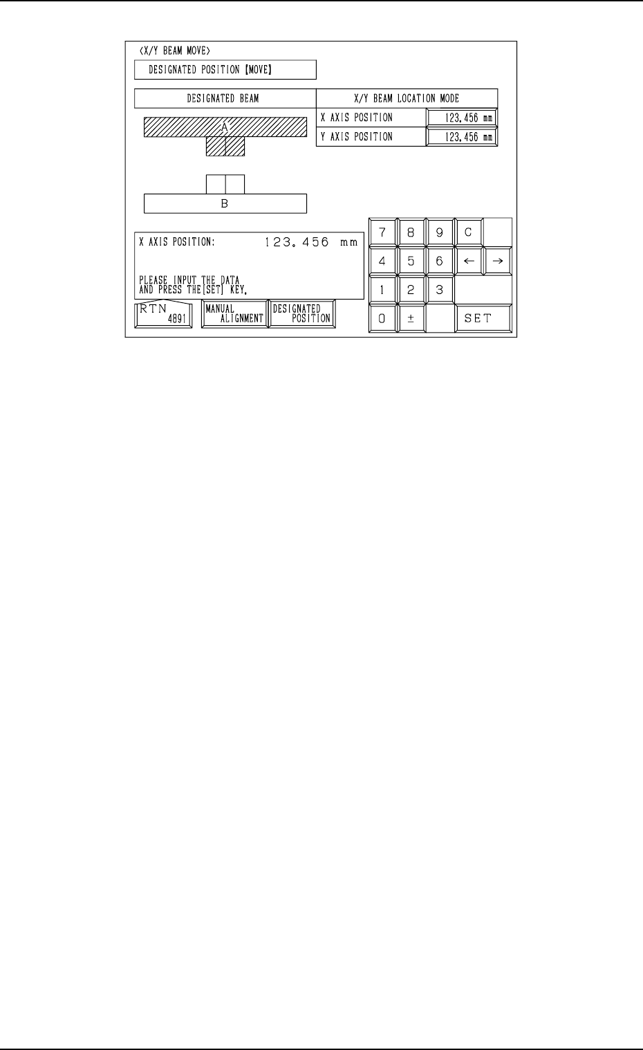
X/Y Beam Movement to Designated Position (Fig. 4C258)
(1) Select the “X AXIS POSITION” and “Y AXIS POSITION” data boxes
under the label “X/Y BEAM LOCATION MODE” and enter parameters
using the ten-key pad.
(2) When the [MOVE] button is pressed, the X/Y beam moves to the desig-
nated position.
Fig. 4C258
0305-001 Tg0860-PM-MM
7.1 P.E.C. RECOG TEST Display
3-131
7.1.2 View on Recognition Monitor
When the “P.E.C. RECOG TEST” display is opened, a recognition range (win-
dow size) appears on the recognition monitor.
Note: When a window size is changed, the captured image also changes on
the recognition monitor.
●
OK Result of Recognition
The X/Y beam moves to the place where a fiducial mark is located at the
camera center and the outline of the mark shape and crosslines are displayed.
The positional deviation (X and Y) of the fiducial mark from the camera
center and the recognition time (TIME) are displayed in the A-marked area
of the window.
(The displayed positional deviation shows the deviation detected before test-
ing.)
Note: The point of intersection of the crosslines is the camera center.
• NG (No Good) Result of Recognition
The outline of mark shape and crosslines are not displayed and the “RE-
SULT OF P.E.C. RECOGNITION” display appears on the touch screen,
showing the result of recognition as “NO GOOD”.
Ref.: Pressing the [RESULT OF RECOG.] key at the “P.E.C. RECOG TEST”
display (Fig. 4C250) also opens the “RESULT OF P.E.C. RECOGNI-
TION” display.
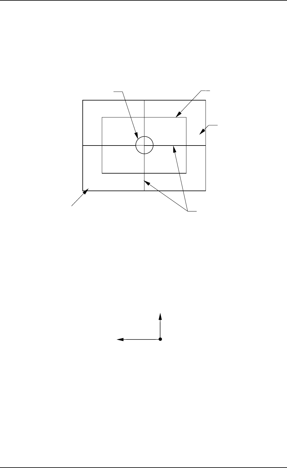
Fig. 4C259
Window
(Recognition Area)
Recognition Range
(Window Size)
Crosslines
Image of Fiducial Mark
X=000 Y=000 TIME=000
A
Y (+)
X (+)
Camera Center
Fig. 4C260
0305-001 Tg0860-PM-MM
7.1 P.E.C. RECOG TEST Display
3-132
7.1.3 Procedure for P.E.C. Recognition Test
(1) Position the P.C.B. to be tested on the P.C.B. positioning section (P Con-
veyor).
• Open the “MANUAL TRANSFER OPERATION” display and posi-
tion the P.C.B. manually. (Hierarchical Sequence: “MANUAL MODE”
Display → “MANUAL TRANSFER OPERATION” Display)
• Confirm that each device is located at its origin.
(2) Set “CAM-A3” (Beam A) or “CAM-B3” (Beam B) in the “P.E.C. RECOG
CAMERA” data box at the “P.E.C. RECOG TEST” display.
When the camera is selected, the P.E.C. recognition lamp illuminates and
the specified camera captures the real image.
(3) Open the “X/Y BEAM MOVE”display (Fig. 4C258) and follow the steps
in “X/Y Beam Movement to Designated Position” to move the P.E.C.
recognition camera to the position of the P.E.C. recognition mark cap-
tured on the recognition monitor.
The parameters to be set here for “X AXIS POSITION” and “Y-AXIS
POSITION” must be the coordinates originated from the P.C.B. position-
ing reference point.
When the fiducial mark (recognition mark) to be recognized does not
enter into the window, open the “X/Y BEAM MOVE” (MANUAL
ALIGNMENT) display and move the camera (the X/Y beam) to the posi-
tion where the mark stays inside the window or open the “P.E.C. RECOG
TEST” display and enlarge the window size.
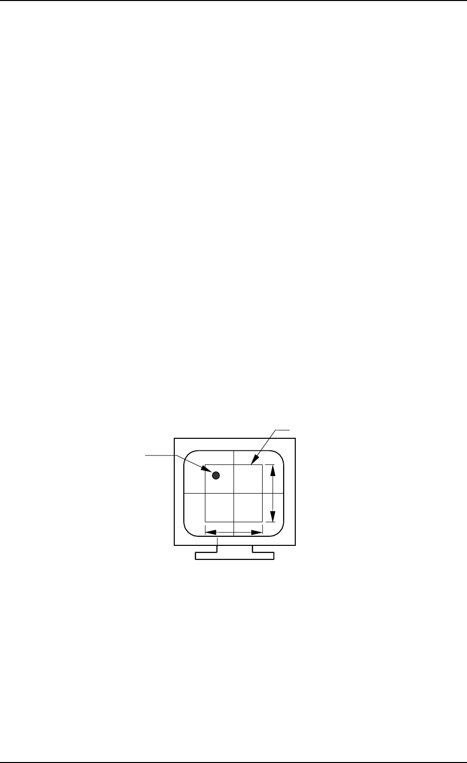
Note: The maximum size of the window is “10 × 10 mm”.
Image on Recognition Monitor (Before Recognition)
(4) Set various parameters for the P.C.B. recognition test.
(MARK TYPE, MARK SIZE, WINDOW SIZE, etc.)
• Select the key for which a parameter should be set.
The background color of the selected key becomes “Blue”.
• Use option keys or the ten-key pad to enter a parameter and press the
[SET] key. Option keys or the ten-key pad appears depending on which
data box is selected.
(Every time the [+] or [−] key beside the labels “GAIN” and “LEVEL”
is pressed, the set parameter increases or decreases one by one. It is not
necessary to press the [SET] key.)
Window
Fiducial Mark
(Recognition Mark)
Max. 10 mm
Max. 10 mm
Fig. 4C261