4OM-1011-002.pdf - 第185页
0305-001 Tg0860-PM-MM 7.1 P .E.C. RECOG TEST Display 3-134 Case: An error was found in the recognition. The details of the error are displayed on the operation monitor . Note: The values X and Y displayed as the results …
0305-001 Tg0860-PM-MM
7.1 P.E.C. RECOG TEST Display
3-133
(5) Select the [P.E.C. RECOG. TEST [MOVE]] key at the “P.E.C. RECOG
TEST” display and press the [MOVE] button. The P.E.C. recognition test
starts.
Check whether the recognition is normally completed or not.
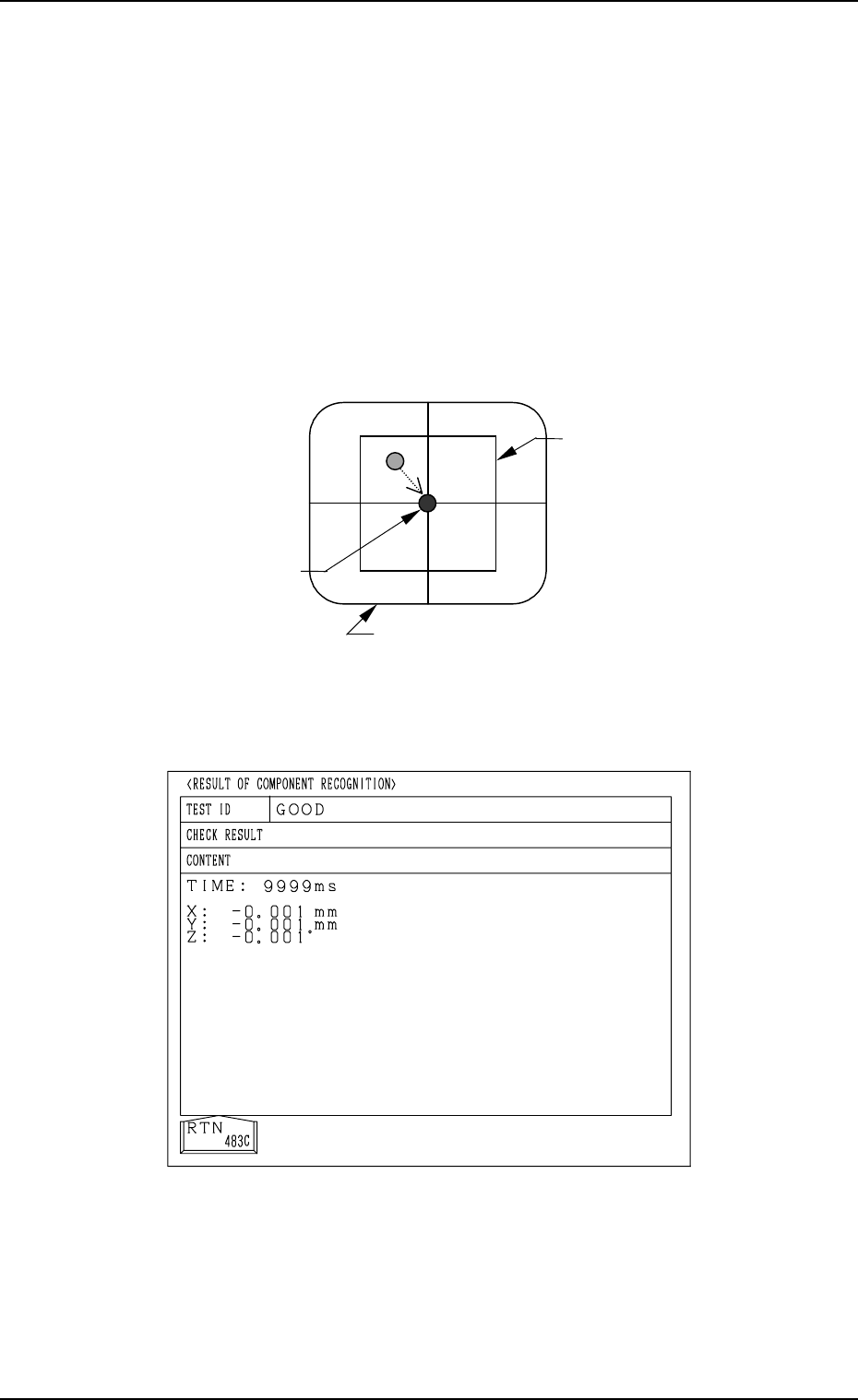
Case: Recognition has completed normally.
• Display on Recognition Monitor
The camera (the X/Y beam) moves automatically until the fiducial mark
lies over the center of the crosslines while the result of the recognition
is being displayed at the bottom of the recognition monitor.
• Result of Recognition
Deviation X : Increments in µm
Y : Increments in µm
Recognition Time (TIME) : Increments in msec
• Display of Operation Monitor
Normal Completion of Recognition
Fig. 4C263
Image on Recognition Monitor (After Recognition)
Fig. 4C262
Window
X =*** Y =*** TIME =***
Result of Recognition
Fiducial Mark
0305-001 Tg0860-PM-MM
7.1 P.E.C. RECOG TEST Display
3-134
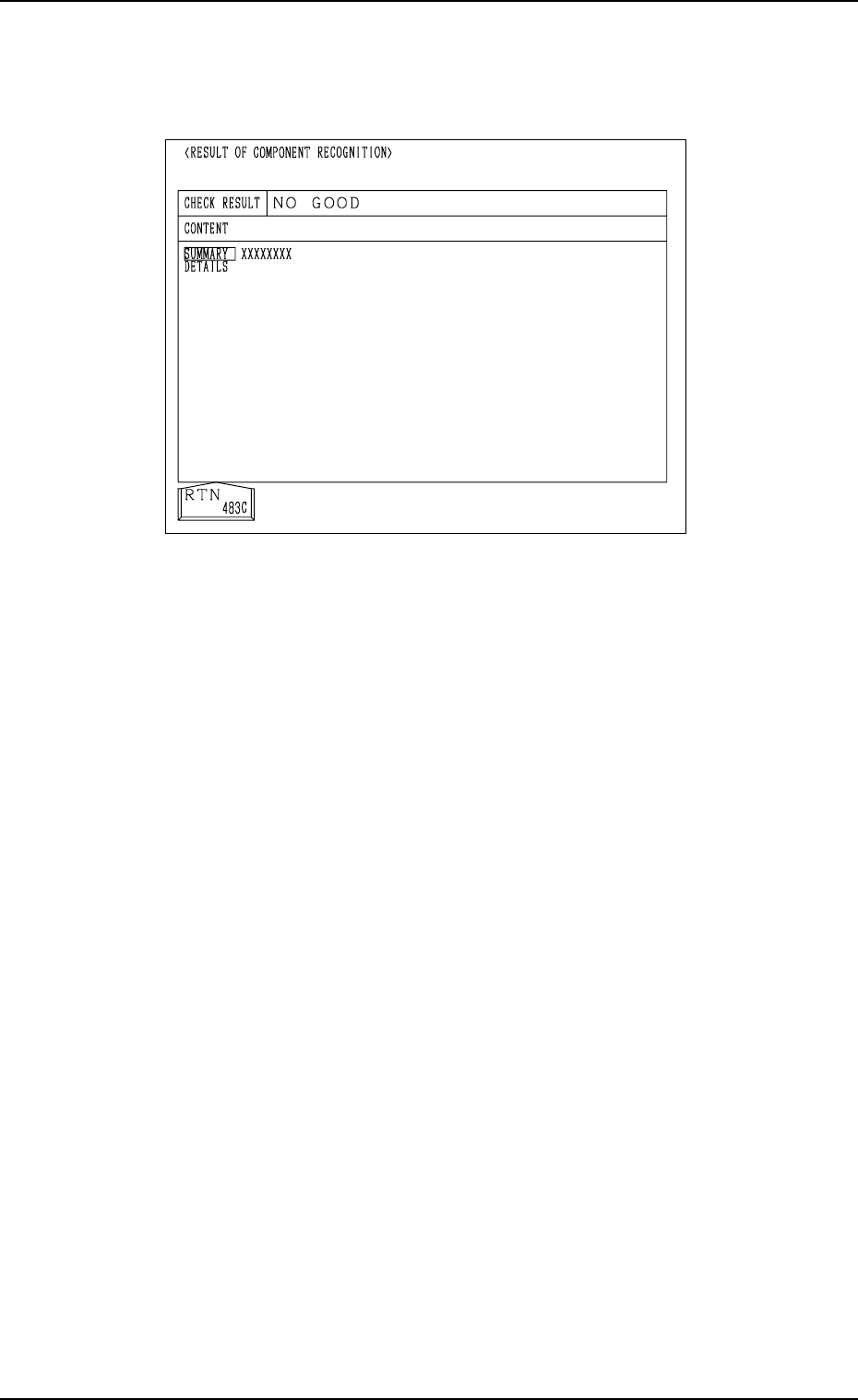
Case: An error was found in the recognition.
The details of the error are displayed on the operation monitor.
Note: The values X and Y displayed as the results of recognition on the
recognition monitor may differ from the values X and Y displayed
on the operation monitor, depending on the offset values of the
camera system.
(6) Press the [RTN] key.
(7) Change the condition according to Steps (3) through (6) and re-perform
the P.E.C. recognition test.
Make the test under the condition diversified by changing the location of
the X/Y beam and various settings.
Ref.: The recognition test can be implemented as many times as required.
The check operation can be made after the fiducial mark is ad-
justed to various positions by moving the X/Y beam (through
manual alignment operation).
(8) Exit from the P.E.C. recognition test operation.
Select the [X/Y BEAM ZERO [MOVE]] key and press the [MOVE] but-
ton.
The X/Y beam is zeroed.
Abnormal Completion of Recognition
Fig. 4C264
0305-001 Tg0860-PM-MM
7.2 COMPONENT RECOG. TEST Display
●
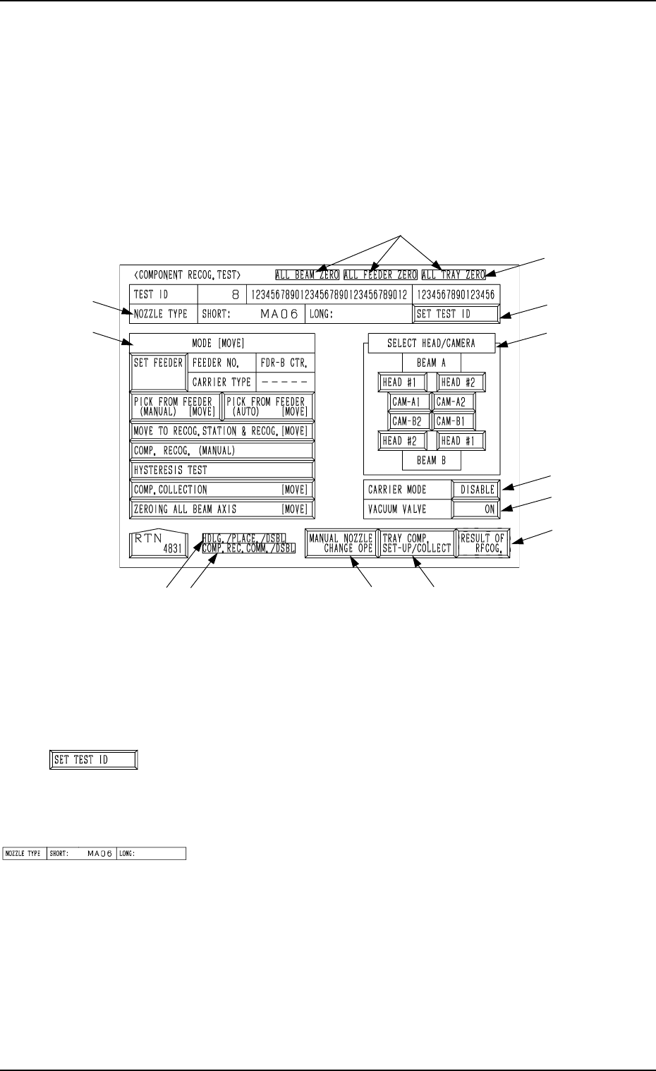
A recognition test can be performed to check whether or not the component
specified in the “TEST ID” text box can be recognized normally.
When the [COMPONENT RECOG TEST] key is pressed at the “DEVICE
TEST” display, the following display appears on the screen.
Note: The -marked function is optional.
Ref.: The yellow and light blue keys indicate that they are linked with other
displays (located in the lower hierarchical structure).
The other keys can be selected and used together with the [MOVE]
button.
*1 [SET TEST ID] Key
When this key is pressed, the “SET TEST ID” display ap-
pears on the screen, enabling the operator to set the compo-
nent ID to be tested as a test ID.
*2 “NOZZLE TYPE”
Displayed is the type of the nozzle specified in the “TEST
ID” text box.
7.2 COMPONENT RECOG. TEST Display
3-135
Fig. 4C265
*1
*4
*6
*5
*9
*8*7
*12
*11
*3
*2
*10
Fig. 4C266
Fig. 4C267