4OM-1011-002.pdf - 第187页
0305-001 Tg0860-PM-MM 7.2 COMPONENT RECOG. TEST Display 3-136 *3 “MODE [MOVE]” [SET FEEDER] Key When this key is pressed, the “COMP . RECOG. TEST - SET FEEDER” display appears on the screen, enabling the operator to set …
0305-001 Tg0860-PM-MM
7.2 COMPONENT RECOG. TEST Display
●
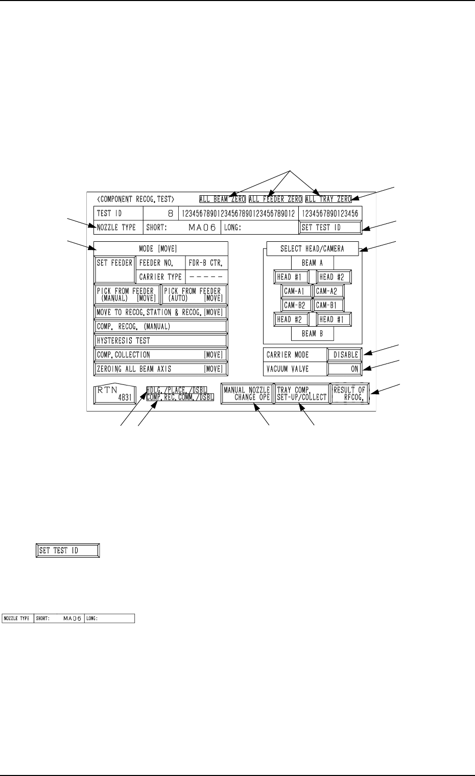
A recognition test can be performed to check whether or not the component
specified in the “TEST ID” text box can be recognized normally.
When the [COMPONENT RECOG TEST] key is pressed at the “DEVICE
TEST” display, the following display appears on the screen.
Note: The -marked function is optional.
Ref.: The yellow and light blue keys indicate that they are linked with other
displays (located in the lower hierarchical structure).
The other keys can be selected and used together with the [MOVE]
button.
*1 [SET TEST ID] Key
When this key is pressed, the “SET TEST ID” display ap-
pears on the screen, enabling the operator to set the compo-
nent ID to be tested as a test ID.
*2 “NOZZLE TYPE”
Displayed is the type of the nozzle specified in the “TEST
ID” text box.
7.2 COMPONENT RECOG. TEST Display
3-135
Fig. 4C265
*1
*4
*6
*5
*9
*8*7
*12
*11
*3
*2
*10
Fig. 4C266
Fig. 4C267
0305-001 Tg0860-PM-MM
7.2 COMPONENT RECOG. TEST Display
3-136
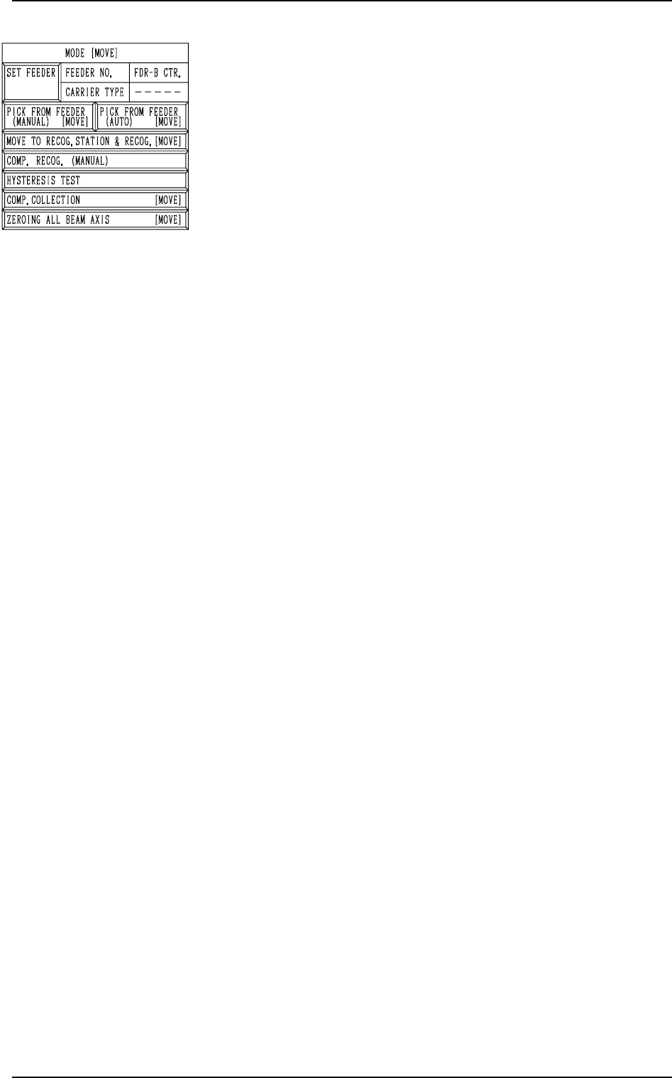
*3 “MODE [MOVE]”
[SET FEEDER] Key
When this key is pressed, the “COMP. RECOG.
TEST - SET FEEDER” display appears on the screen,
enabling the operator to set the feeder from which
the component to be tested should be taken out.
[PICK FROM FEEDER (MANUAL) [MOVE]] Key
This key is used to manually attach a component.
When this key is selected and the [MOVE] button is
pressed, the designated head moves to the position
of the specified feeder No. and the vacuum valve is
turned ON.
[PICK FROM FEEDER (AUTO) [MOVE]] Key
This key is used to automatically take out a compo-
nent.
When this key is selected and the [MOVE] button is
pressed, the designated head moves to the position
of the specified feeder No. and picks up a compo-
nent from the feeder.
[MOVE TO RECOG. STATION & RECOG. [MOVE]] Key
When this key is selected and the [MOVE] button is
pressed, the designated head moves to the position
of the component recognition camera and a compo-
nent recognition test is performed.
Note: When the component pick-up operation is not
completed, this key cannot be selected.
[COMP. RECOG. (MANUAL)] Key
When this key is pressed, the “COMPONENT REC-
OGNITION TEST” display appears on the screen,
enabling the operator to correct the posture of the
picked component, set the lighting for recognition,
and implement the component recognition operation.
Note: When the component pick-up operation is not
completed, this key cannot be selected.
[HYSTERESIS TEST] Key
When this key is pressed, the “HYSTERESIS TEST”
display appears on the screen, enabling the operator
to verify the beam speed reduction and the θ-
ro0tational speed reduction (specified in the compo-
nent library data) for component picks and set some
supplementary data in relation to the beam and rota-
tional speed reduction.
[COMP. COLLECTION [MOVE]] Key
This key is used to collect (discharge) component
and zero the X/Y beam.
Components are discharged to the component dis-
charge box near the X/Y beam or to the component
discharge conveyor (option).
Note: Turn off the vacuum valve after the compo-
nent collection is completed.
The display cannot be resumed when the
vacuum valve is kept “ON”.
[ZEROING ALL BEAM AXIS [MOVE]] Key
Both Beams A and B are zeroed.
When this key is selected and the [MOVE] button is
pressed, the beams are zeroed.
Fig. 4C268
0305-001 Tg0860-PM-MM
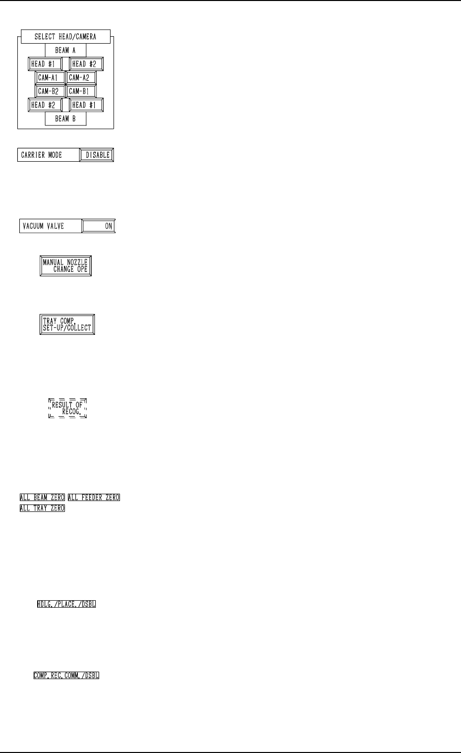
*4 “SELECT HEAD/CAMERA”
The keys in this group box can be used to select the head to
take out components and the component recognition cam-
era to capture an image.
Notes: (a) After the feeder is set, the head which can be
selected is limited.
(b) The head and camera to be bypassed are dis
played in red, indicating that they cannot be
selected.
*5 “CARRIER MODE”
It can be determined whether or not the component feeding
operation of the feeder and the supply operation of the multi-
layer tray feeder must be implemented.
“ENABLE” or “DISABLE” can be selected.
*6 “VACUUM VALVE”
The vacuum for the nozzle can be turned ON or OFF.
*7 [MANUAL NOZZLE CHANGE OPE] Key
When this key is pressed, the “MANUAL NOZZLE
CHANGE OPERATION” display appears on the screen,
enabling the operator to attach or store the nozzle.
*8 [TRAY COMP. SET-UP/COLLECT] Key (Option)
When this key is pressed, the “COMPONENT RECOG.
TEST - TRAY COMPONENT SUPPLY/STORAGE” dis-
play appears on the screen, enabling the operator to draw
out or store the pallet drawing and change the tray pick-up
matrix.
*9 [RESULT OF RECOG.] Key
When this key is pressed, the “RESULT OF COMPONENT
RECOGNITION” display appears on the screen, enabling
the operator to check the results of the component recogni-
tion test.
Note: This key appears after the component recognition
test is performed.
*10 “Set Condition”
The background color becomes green when the set-up op-
erations of “ALL BEAM ZERO”, “ALL FEEDER
ZERO”, and “ALL TRAY ZERO” are completed. Other-
wise, the backgrounds have no color.
Note: When the recognition test is performed with each
section not set up, it may not be implemented cor-
rectly.
*11 “HDLG./PLACE./DSBL”
This appears when “DISABLE” is set in the “HAN-
DLING/PLACEMENT MODE” data box at the “TEST
MODE” display.
The operation is performed normally.
*12 “COMP. REC. COMM./DSBL”
This appears when “DISABLE” is set in the “COMPO-
NENT RECOGNITION” data box at the “TEST MODE”
display.
(Background Color: Light Red)
The recognition processing is made normally.
7.2 COMPONENT RECOG. TEST Display
3-137
Fig. 4C269
Fig. 4C270
Fig. 4C271
Fig. 4C272
Fig. 4C273
Fig. 4C274
Fig. 4C275
Fig. 4C276
Fig. 4C277