4OM-1011-002.pdf - 第193页
0305-001 Tg0860-PM-MM T o select the feeder number referring to the current program (com- ponent data) (1 ) Select the [FDR. - A 101-], the [FDR. - B 201-], the [TRA Y-L 301-] (option), or the [TRA Y-R 601-] (option) key…
0305-001 Tg0860-PM-MM
7.2 COMPONENT RECOG. TEST Display
7.2.2 COMP. RECOG. TEST - SET FEEDER Display
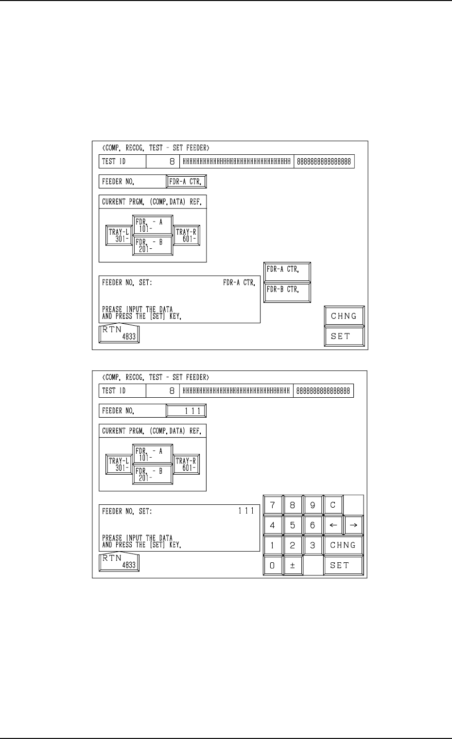
• This display allow the operator to specify the slot No. of the feeder from
which the component should be taken out for the component recognition
test or the position where the component should be attached manually.
When the [SET FEEDER] key is pressed at the “COMPONENT RECOG.
TEST” display, the following display appears on the screen.
The contents of the display change according to the selected feeder No.
To manually attach a component
(1) Select the [FDR. - A 101-] or the [FDR. -B 201-] key located under “CUR-
RENT PRGM. (COMP. DATA) REF.”.
(2) Select the [FDR-A CTR.] or the [FDR-B CTR.] key and press the [SET]
key.
A component can be attached manually above the component discharge
box or the component discharge conveyor (option).
To directly enter the feeder No.
(1) Press the [CHNG] key at the display (Fig. 4C290).
(2) Enter the feeder No., using the ten-key pad and press the [SET] key.
Fig. 4C290
Fig. 4C291
3-141
0305-001 Tg0860-PM-MM
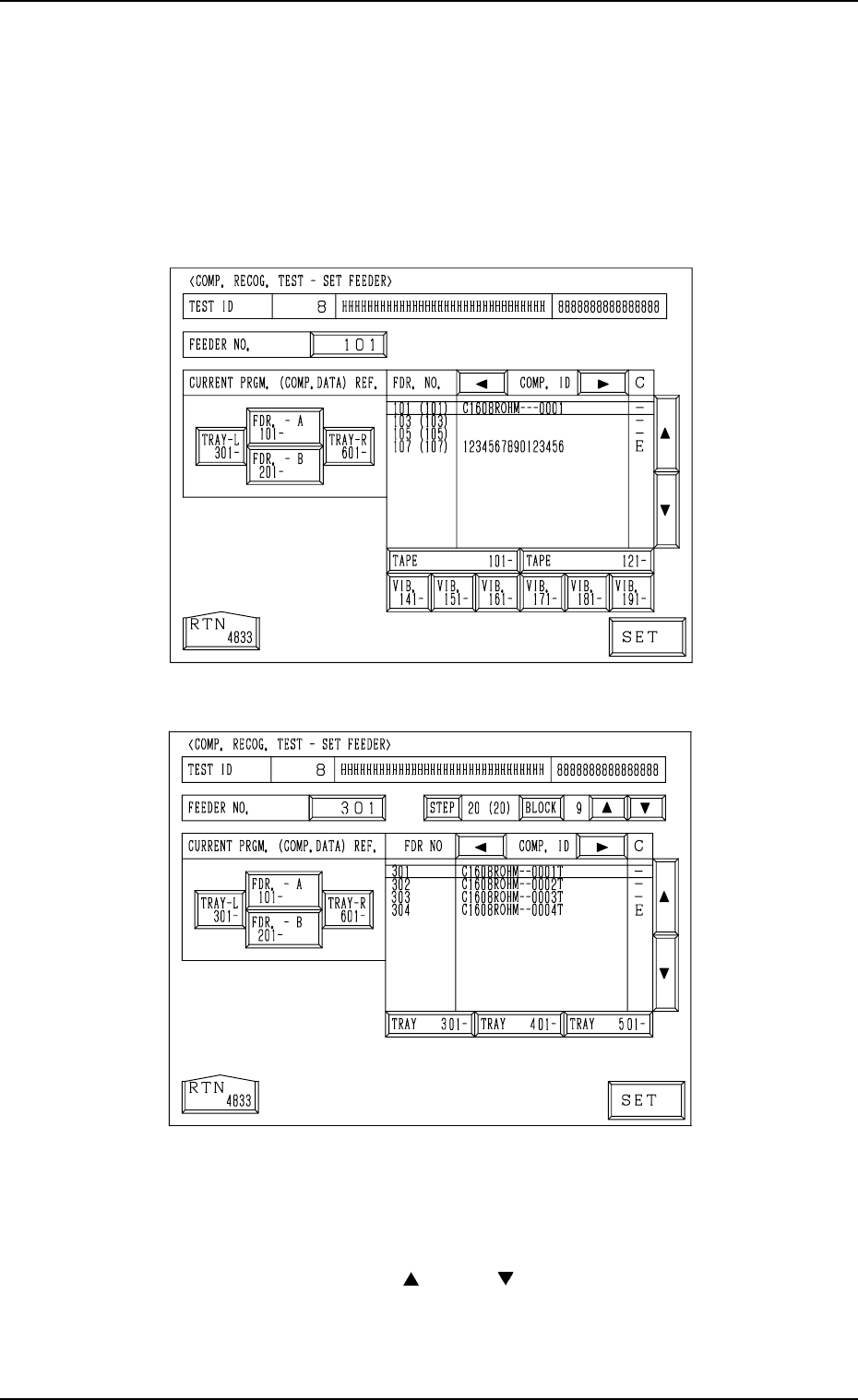
To select the feeder number referring to the current program (com-
ponent data)
(1) Select the [FDR. - A 101-], the [FDR. - B 201-], the [TRAY-L 301-]
(option), or the [TRAY-R 601-] (option) key located under “CURRENT
PRGM. (COMP. DATA) REF.”.
The keys labeled with feeder Nos. (Nos. classified in every one hundreds)
are displayed.
[FDR. - A 101-] and [FDR. - B 201-] Keys
[TRAY-L 301-] and [TRAY-R 601-] Keys
(2) Press the unit key related to the feeder No. to be set.
The list of component IDs is displayed.
Note: It is impossible to select the unit for which no data is registered in
the component data of the current pattern program data.
(3) Move the cursor with the [ ] or the [ ] key and select the feeder No.
Then, press the [SET] key.
• When the data for the multi-layer tray feeder (option) is selected, the
related step and block numbers must also be set, using the [STEP] and
the [BLOCK] keys.
7.2 COMPONENT RECOG. TEST Display
3-142
Fig. 4C292
Fig. 4C293
0305-001 Tg0860-PM-MM
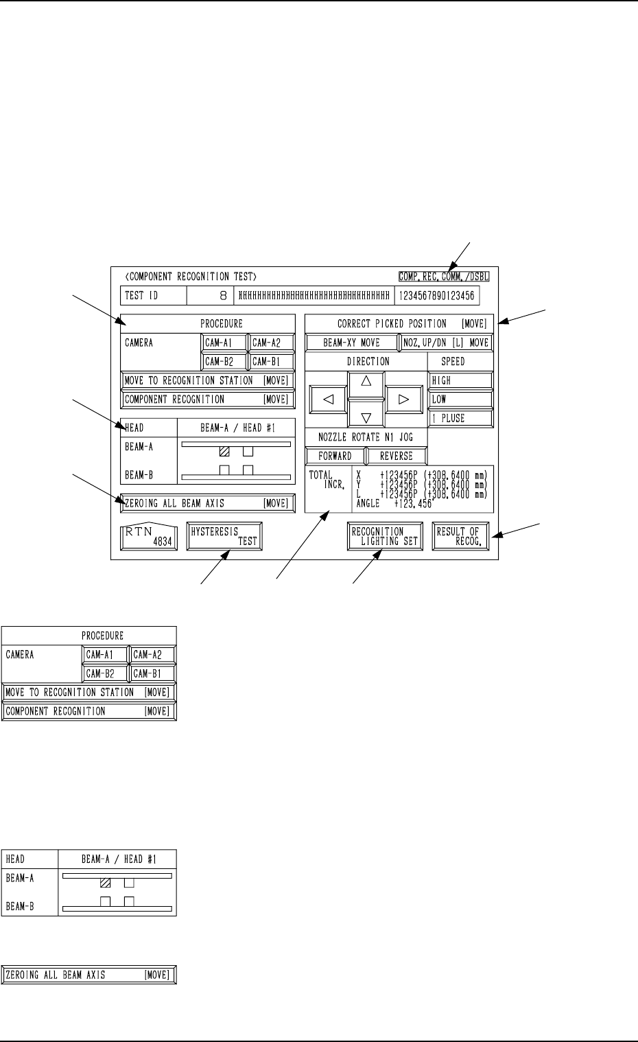
7.2.3 COMPONENT RECOGNITION TEST Display
• This display allows the operator to correct the posture of the picked compo-
nent, set the lighting for recognition, and implement the component recog-
nition.
When the [COMP. RECOG. (MANUAL)] key is pressed at the “COMPO-
NENT RECOG. TEST” display, the following display appears on the screen.
Note: When the component pick-up operation is not completed, this key can-
not be selected.
*1 “PROCEDURE” and “CAMERA”
Select the component recognition camera to capture
an image.
[MOVE TO RECOGNITION STATION [MOVE]] Key
When this key is selected and the [MOVE] button is
pressed, the designated head moves to the position
of the specified component recognition camera.
[COMP. RECOG. (MANUAL)]] Key
When this key is selected and the [MOVE] button is
pressed, the component recognition test is imple-
mented.
*2 “HEAD”
The head which has picked up a component is displayed in
green.
*3 [ZEROING ALL BEAM AXIS [MOVE]] Key
This key is used to zero both Beams A and B.
When this key is selected and the [MOVE] button is pressed,
the beams are zeroed.
7.2 COMPONENT RECOG. TEST Display
3-143
*9
*4
*7
*6
*5
*3
*2
*1
*8
Fig. 4C294
Fig. 4C295
Fig. 4C296
Fig. 4C297