4OM-1011-002.pdf - 第195页
0305-001 Tg0860-PM-MM *4 CORRECT PICKED POSITION [MOVE] The posture of the picked component can be corrected while the movement is being checked on the recognition moni- tor . [BEAM-XY MOVE] Key This key is used to corre…
0305-001 Tg0860-PM-MM
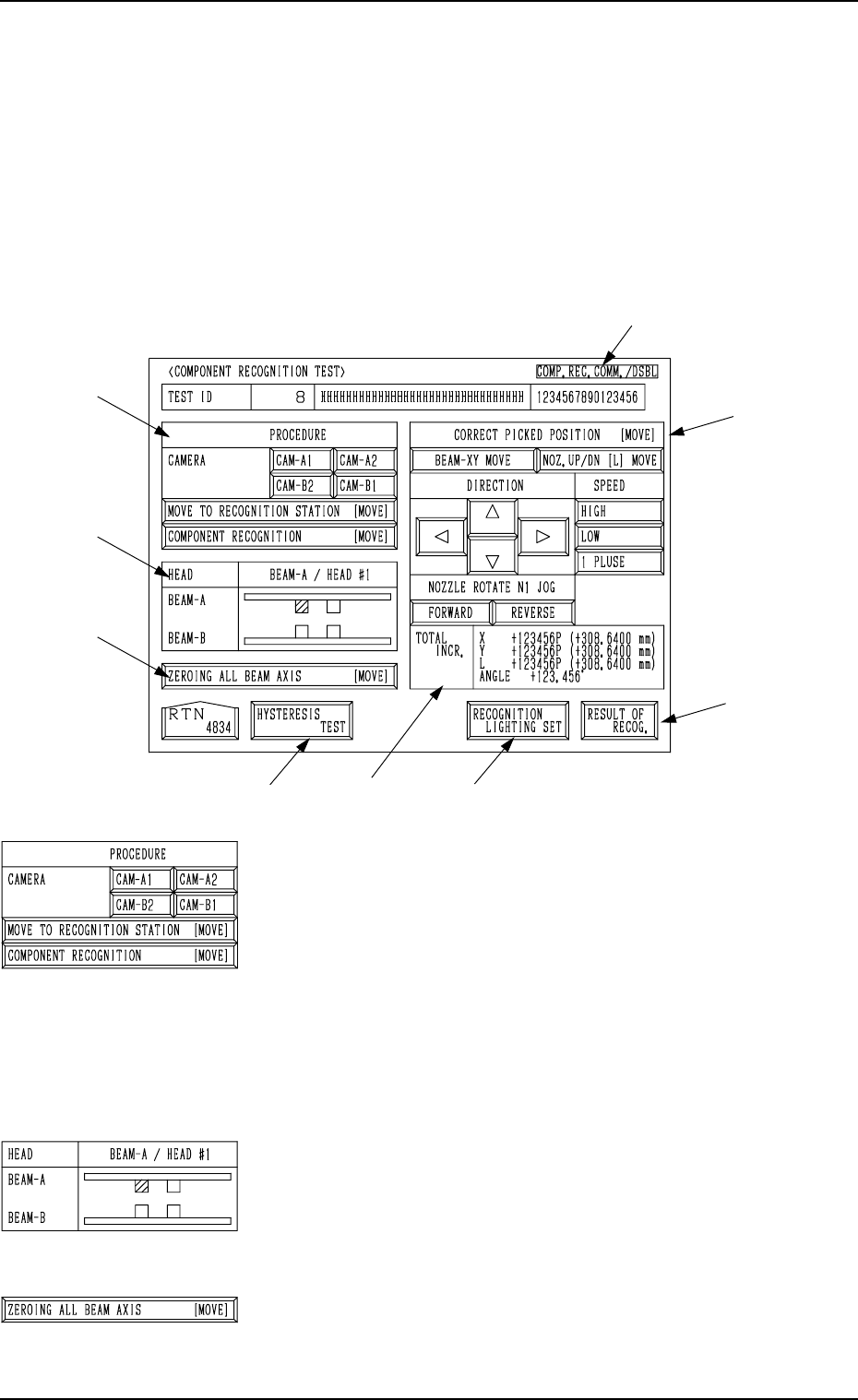
7.2.3 COMPONENT RECOGNITION TEST Display
• This display allows the operator to correct the posture of the picked compo-
nent, set the lighting for recognition, and implement the component recog-
nition.
When the [COMP. RECOG. (MANUAL)] key is pressed at the “COMPO-
NENT RECOG. TEST” display, the following display appears on the screen.
Note: When the component pick-up operation is not completed, this key can-
not be selected.
*1 “PROCEDURE” and “CAMERA”
Select the component recognition camera to capture
an image.
[MOVE TO RECOGNITION STATION [MOVE]] Key
When this key is selected and the [MOVE] button is
pressed, the designated head moves to the position
of the specified component recognition camera.
[COMP. RECOG. (MANUAL)]] Key
When this key is selected and the [MOVE] button is
pressed, the component recognition test is imple-
mented.
*2 “HEAD”
The head which has picked up a component is displayed in
green.
*3 [ZEROING ALL BEAM AXIS [MOVE]] Key
This key is used to zero both Beams A and B.
When this key is selected and the [MOVE] button is pressed,
the beams are zeroed.
7.2 COMPONENT RECOG. TEST Display
3-143
*9
*4
*7
*6
*5
*3
*2
*1
*8
Fig. 4C294
Fig. 4C295
Fig. 4C296
Fig. 4C297
0305-001 Tg0860-PM-MM
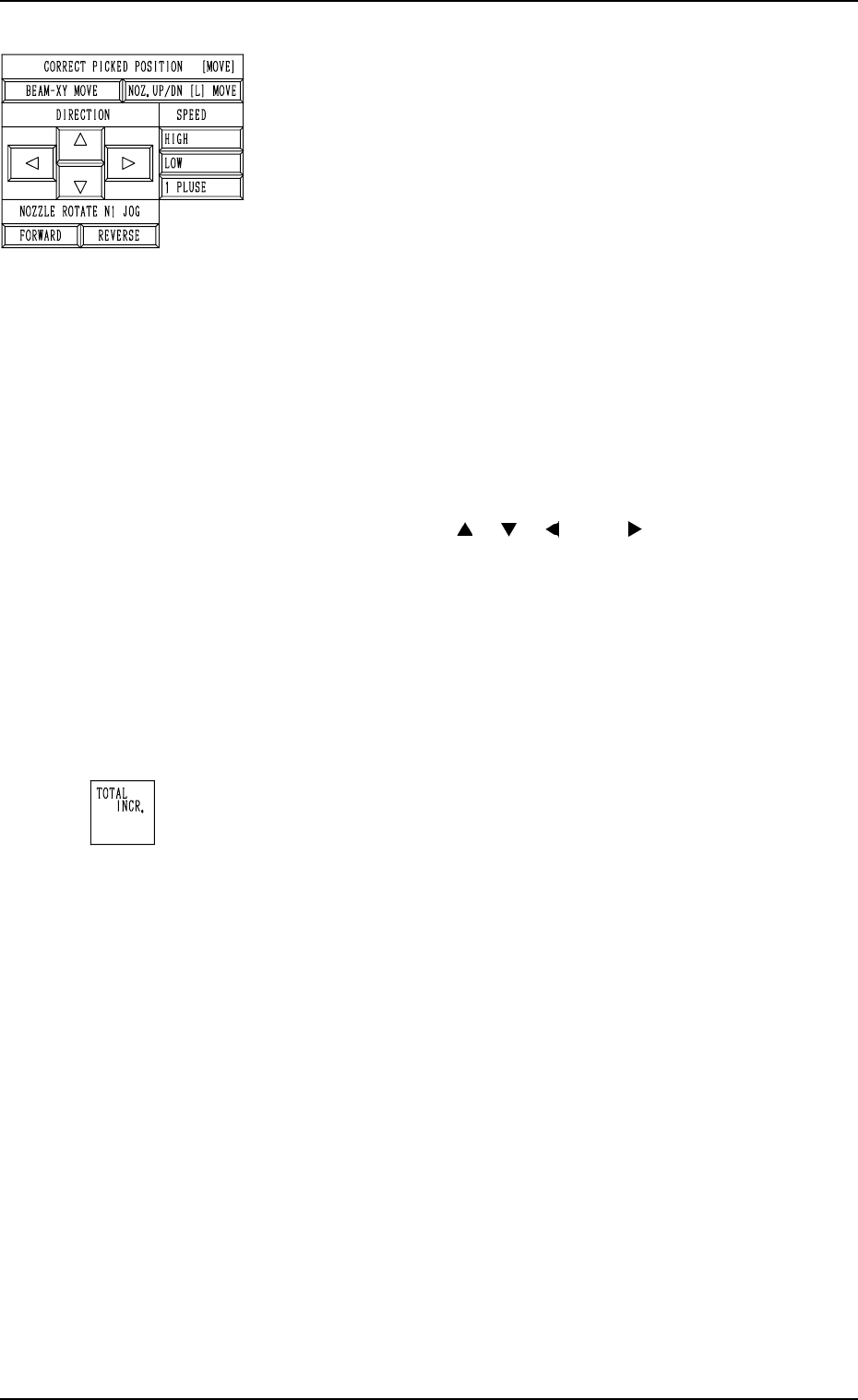
*4 CORRECT PICKED POSITION [MOVE]
The posture of the picked component can be corrected while
the movement is being checked on the recognition moni-
tor.
[BEAM-XY MOVE] Key
This key is used to correct the posture of the picked
component by moving it in the X/Y direction.
When the direction and speed are specified by using
the keys located under “DIRECTION” and “SPEED”
and the [MOVE] button is pressed after this key is
selected, the beam moves in the X/Y direction.
[NOZ. UP/DN [L] MOVE] Key
This key is used to correct the posture of the picked
component by moving it up or down (L direction).
When the direction and speed are specified by using
the keys located under “DIRECTION” and “SPEED”
and the [MOVE] button is pressed after this key is
selected, the nozzle moves up or down (L direction).
“DIRECTION” [ ], [ ], [ ], and [ ] Keys
These keys are used to select the direction in which
the head should be moved.
“SPEED” [HIGH], [LOW], and [1 PULSE] Keys
These keys are used to select the speed at which the
head should be moved.
“NOZZLE ROTATE N1 JOG” [FORWARD] and
[REVERSE] Keys
These keys are used to select the direction in which
the head should be rotated.
*5 “TOTAL INCR.”
Displayed is the accumulated total as the result of the “COR-
RECT PICKED POSITION [MOVE]” operation.
7.2 COMPONENT RECOG. TEST Display
3-144
Fig. 4C298
Fig. 4C299
0305-001 Tg0860-PM-MM
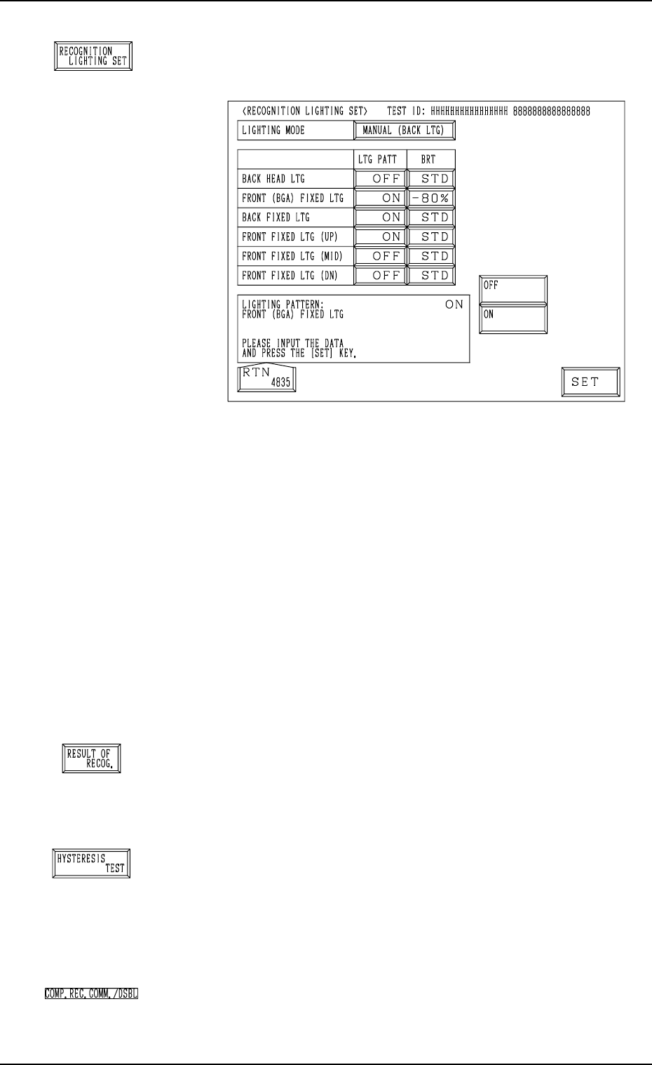
*6 [RECOGNITION LIGHTING SET] Key
When this key is pressed, the “RECOGNITION LIGHT-
ING SET” display appears on the screen.
The default of “Recognition Lighting” is set as the speci-
fied test library data.
If this data is edited, it is not regarded as test library data
but used temporarily as operation data.
Notes: (a) When “MANUAL (XXX)” is not set in the
“LIGHTING MODE” data box, nothing re-
lated to the lighting pattern (“LTG PATT”) and
the brightness (“BRT”) appears for each light-
ing system in this display.
(b) The test library data can be changed at any
timing as long as the machine is not running.
However, when the “SET TEST ID” display
appears on the screen, the parameters changed
temporarily in the “PICK-UP LEVEL”, the
“PICK-UP LOCATION ADJUSTMENT”,
and the “LIGHTING MODE” data boxes are
reset to the defaults.
*7 [RESULT OF RECOG.] Key
When this key is pressed, the “RESULT OF COMPONENT
RECOGNITION” display appears on the screen, enabling
the operator to check the result of the component recogni-
tion operation.
*8 [HYSTERESIS TEST] Key
When this key is pressed, the “HYSTERESIS TEST” dis-
play appears on the screen, enabling the operator to verify
the beam speed reduction and the θ-rotational speed reduc-
tion (specified in the component library data) for compo-
nent picks. Some supplementary data can also be set in re-
lation to the beam and rotational speed reduction.
*9 “COMP. REC. COMM./DSBL”
The background color becomes light red when “DISABLE”
is set in the “COMPONENT RECOGNITION” data box at
the “TEST MODE” display.
7.2 COMPONENT RECOG. TEST Display
3-145
Fig. 4C301
Fig. 4C300
Fig. 4C302
Fig. 4C303
Fig. 4C304