4OM-1011-002.pdf - 第198页
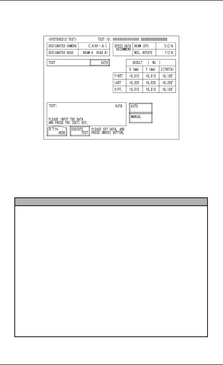
0305-001 Tg0860-PM-MM 7.2 COMPONENT RECOG. TEST Display 3-147 When “AUTO” is set in the “TEST” data box at the “HYSTERESIS TEST” display (Fig. 4C305), the following display appears on the screen. Operation Procedure (1) …
0305-001 Tg0860-PM-MM
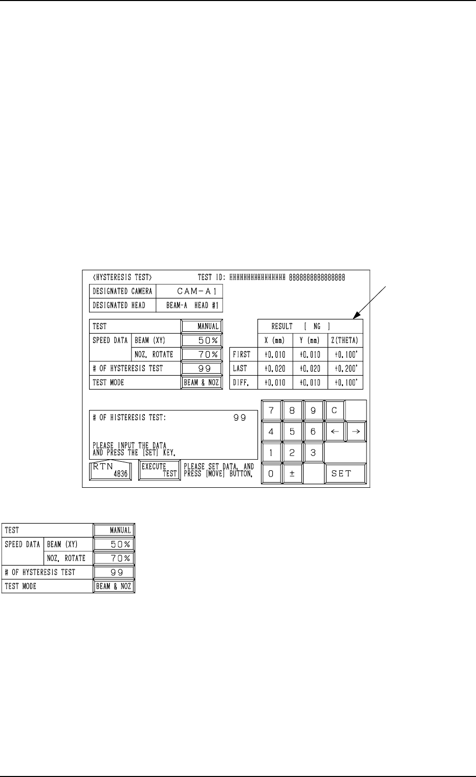
7.2.4 HYSTERESIS TEST Display
• This display allows the operator to verify the beam speed reduction and the
θ-rotational speed reduction (specified in the component library data) for
component picks. Some supplementary data can also be set in relation to the
beam and rotational speed reduction.
• “MANUAL” or “AUTO” can be selected as a hysteresis test mode.
When “MANUAL” is set in the “TEST” data box, parameters must be set in
the “SPEED DATA”, “# OF HYSTERESIS”, and “TEST MODE” data boxes
to determine how the hysteresis test should be performed manually.
When “AUTO” is set, the speed increases gradually and the test operation is
performed repeatedly in a specific pattern.
When the [HYSTERESIS TEST] key is pressed at the “COMPONENT REC-
OGNITION TEST” display, the following display appears on the screen.
TEST
“MANUAL” or “AUTO” can be set in this data box.
SPEED DATA BEAM (XY), NOZ. ROTATE
Parameters can be set to specify how much the test speed
should be reduced.
• Data Input Range
One of the 10 steps (“FULL SPEED” to “90%”) can be
selected.
##
##
# OF HYSTERESIS TEST
• Data Input Range
1 to 99
TEST MODE
• Options
“BEAM & NOZ”
“BEAM (XY)”
“NOZ. ROTATE”
7.2 COMPONENT RECOG. TEST Display
3-146
A
Fig. 4C305
Fig. 4C306
0305-001 Tg0860-PM-MM
7.2 COMPONENT RECOG. TEST Display
3-147
When “AUTO” is set in the “TEST” data box at the “HYSTERESIS TEST”
display (Fig. 4C305), the following display appears on the screen.
Operation Procedure
(1) Set parameters required for the brandish test in the data boxes.
(2) When the [EXECUTE TEST] key is selected and the [MOVE] button is
pressed, the hysteresis test starts. A fter the test is over, the results of test
appear in section A.
Reference
When “AUTO” is set in the “TEST” data box for the components having the following
characteristics, the parameters (the parameters calculated in hysteresis tests) in the
“BEAM (XY)” and “NOZ. ROTATE” text boxes of the label “SPEED DATA
RECOMMENDED” may vary greatly every time a test is performed.
• Components are picked up while the vacuum may likely be leaking slightly.
• Components are picked up eccentrically (off-centered) with big mass.
• Compared with the nozzle size, the component is relatively large in size and big in
mass.
It will be difficult to make a test in stable condition due to the change in the state of
picked components during test operations.
Therefore, obtain the stable speed reduction data by performing the test repeatedly in
the “MANUAL” mode (“MANUAL” set in the “TEST” data box).
Operation Procedure
(1) Set “MANUAL” in the “TEST” data box at the “HYSTERESIS TEST” display.
(2) Set “90%” (low speed) as the designated speed reduction and make a test.
(3) Increase the designated speed reduction according to the situational changes in the
test.
(4) Repeat the test until the difference in the results of the test reduces.
Fig. 4C307
0305-001 Tg0860-PM-MM
7.2.5 COMPONENT RECOG. TEST - TRAY COMPONENT
SUPPLY/STORAGE Display (Option)
• This display allows the operator to draw out and store the tray components
(pallet) and change the tray pick-up matrix when the component recognition
test is made on the tray components.
When the [TRAY COMP. SET-UP/COLLECT] key is pressed at the “COM-
PONENT RECOG. TEST” display, the following display appears on the screen.
*1 “FEEDER NO.”
Displayed is the feeder No. which was set at the display
(Fig. 4C290).
*2 [STEP] and [BLOCK] Keys
Displayed are the step and block numbers which were set
at the display (Fig. 4C290).
When there are several steps and blocks, set the numbers
with the [ ] or the [ ] key.
*3 [DRAWING CARRIAGE [MOVE]] Key
When this key is selected and the [MOVE] button is pressed,
the pallet selected in *1 and *2 is drawn out.
*4 [STORING CARRIAGE [MOVE]] Key
When this key is selected and the [MOVE] button is pressed,
the drawn pallet is stored.
*5 [ZEROING TRAY UNIT [MOVE]] Key
This key is used to zero the multi-layer tray feeder
(option).
When this key is selected and the [MOVE] button is pressed,
the zeroing operation starts.
*6 “PICK UP TRAY MATRIX (99, 99)”
The matrix for the subsequent component pick can be speci-
fied.
The numerical values in parentheses show the maximum
ones for the selected tray (block).
*7 “TRAY-L” and “TRAY-R”
It is shown which mode “[NEUTRAL], [LINE], or [LO-
CAL]” the right and left multi-layer tray feeders are in and
whether they are zeroed or not.
When the multi-layer tray feeder is zeroed, “” appears.
Note: The condition of the disconnected multi-layer tray
feeder is not shown.
7.2 COMPONENT RECOG. TEST Display
3-148
*2
*6
*1
*3
*4
*5
*7
Fig. 4C308
Fig. 4C309
Fig. 4C310
Fig. 4C311
Fig. 4C312
Fig. 4C313
Fig. 4C314
Fig. 4C315